
Method and apparatus for electrostatic spray deposition for a solid oxide fuel cell

Inactive Publication Date: 2008-02-07
ILLINOIS INSTITUTE OF TECHNOLOGY
View PDF6 Cites 14 Cited by
  • Summary
  • Abstract
  • Description
  • Claims
  • Application Information

AI Technical Summary

Benefits of technology

[0018] One interest in Category 3 processes is that, in principle, they avoid this disadvantage of the Category 1 and 2 processes and are based on more rational one-step process without introducing pre-fabricated particles. Particle formation, followed by agglomeration on the substrate, is either side-stepped, as in EVD and CVD, or carried out in situ, as in CADT and to some extent in PE-MOCVD. The in-situ formation of particle-precursors, nuclei, or particles takes place in a gaseous medium or plasma, and this process can be designed and controlled, like in a chemical reactor. Likewise, particle agglomeration onto the substrate can be controlled by suitable regime of convection, diffusion, and migration in an electric field, if applicable. But one disadvantage of some of the Category 3 processes is that the very complicated nature of the gas-to-solid process kinetics makes design optimization and control difficult. Also, in practice, the deposition rates are low. In cases where the gas-phase transport and reaction processes are relatively straightforward, as in EVD, the growth rate may be slow because it is controlled by solid-state diffusion in the deposit film.
[0022] ESD uses electrostatic charging to disperse the liquid. One advantage of electrostatic dispersion is that the unipolar, usually positive charge helps to achieve a very small drop size. The charge also prevents coalescence of drops and thus agglomeration of particles, during flight. Also, the electric field provides a high degree of control over the direction of flight and the distribution of the rate of deposition over the substrate. Indirectly, the electrostatic technique, because it can produce extremely fine, almost uniformly sized drops, also provides significant control over the extent of the precursor reaction and the morphology, such as the crystal structure and the grain size, of the product particle formed. Also, if very small drops and thus particles are generated, then elevated temperatures are not necessary to achieve a heterogeneous reaction and interdiffusion necessary for satisfactory uniformity of the product particles and the deposit layer. High gas temperatures in the reactor, typical for spray pyrolysis, can then be avoided, and even post-deposition annealing may be unnecessary. Thus, the ESD process of this invention seems particularly suited to electrolyte deposition at relatively low temperatures, as desirable for the IT-SOFC.
[0024] The ESD technique can be used to prepare tetragonal zirconia films with simple set-up, a wide choice of precursors, a relatively large film growth rate, an ambient atmosphere operation, a good control of the morphology of the deposited layers and a good control of stoichiometry compared to deposition techniques such as RF sputtering, sot-gel method, CVD or MOCVD, and injection-LPCVD.

Problems solved by technology

However, without tight control of particle-size distribution and rheology of slurries, the Category 1 processes lack the required quality associated with deposit microstructure, particularly uniformity.
However, the deposits produced are usually not 100% or completely dense and thus require some post-process annealing.
This adds to the cost of the plasma process, which is relatively expensive.
However, the deposition rate of sputtering processes is far less than those of spray processes, which is one disadvantage in fabricating other than the thinnest membranes.

Method used


Image

  • Method and apparatus for electrostatic spray deposition for a solid oxide fuel cell
  • Method and apparatus for electrostatic spray deposition for a solid oxide fuel cell
  • Method and apparatus for electrostatic spray deposition for a solid oxide fuel cell

Examples


Embodiment Construction

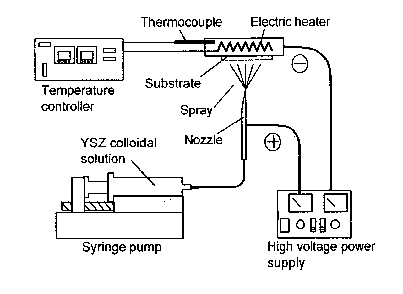
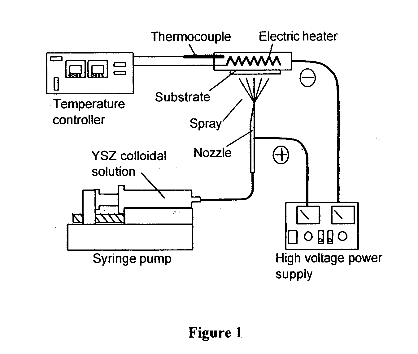
[0039] YSZ deposition can be conducted using suspensions of YSZ powder in organic fluids. ESD is a versatile technique that can be adapted to both solutions and suspensions or emulsions, and to various organic and mixed aqueous / organic solvents or electrolyte solutions. For YSZ depositions, there are two main possibilities. One possibility is to use spray deposition from a solution of a precursor. Another possibility is to use colloidal or near-colloidal suspensions of YSZ or of yttria and zirconia separately. Each approach has its own merits.

[0040] In one embodiment of this invention, a colloidal suspension of YSZ is used. Advantages of ESD using a colloidal solution include: (1) that no chemical reaction occurs during the dispersion and deposition process, and thus optimization of operating conditions is simpler and the chemical composition of the deposit is a priori uniform; (2) that low-temperature operation is adequate because breakdown or reaction of precursors, requiring hig...


PUM


Abstract

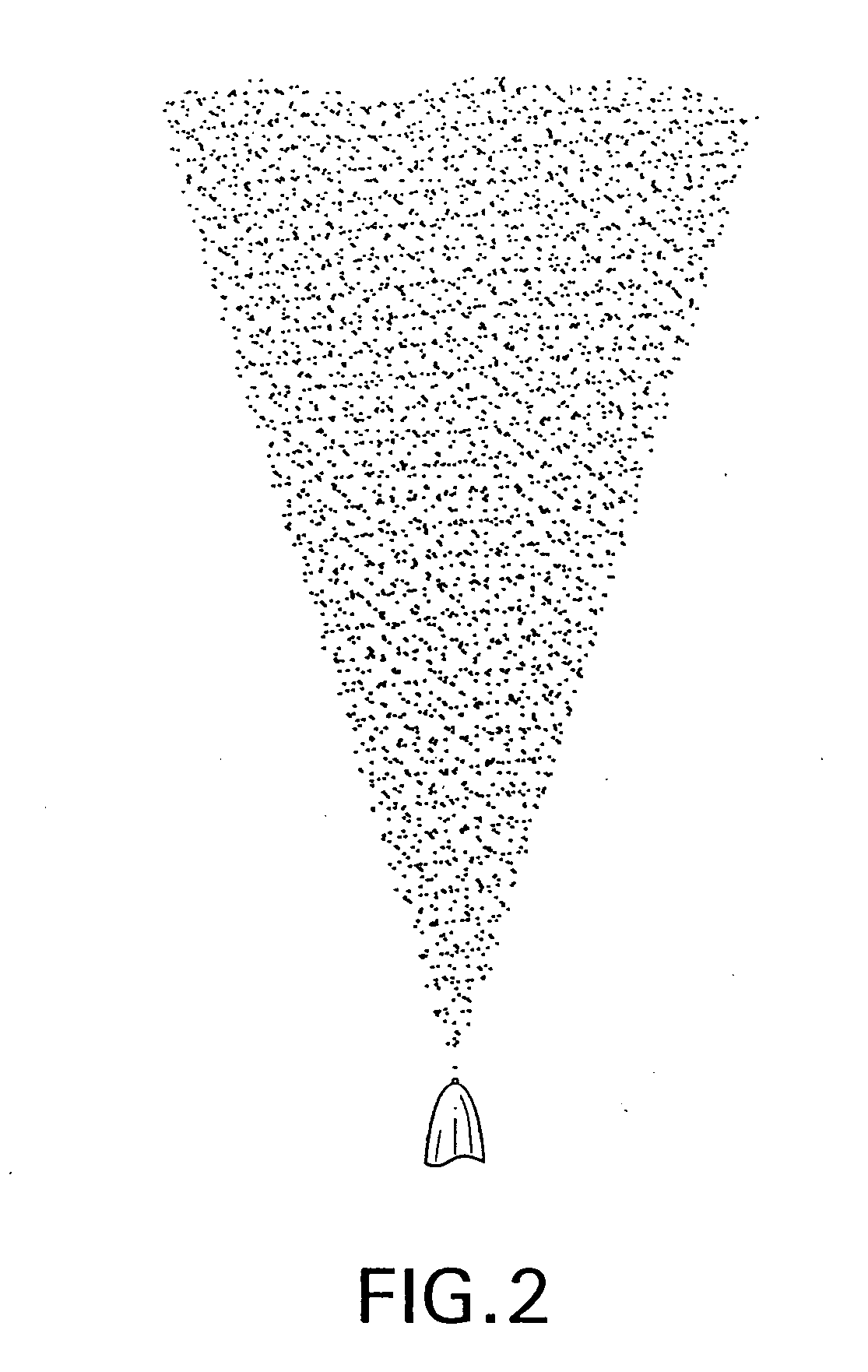
A method and apparatus for electrostatic spray deposition (ESD) for fabricating a thin-layer yttria-stabilized zirconia (YSZ) electrolyte on a solid oxide fuel cell (SOFC) anode substrate constructed of nickel-YSZ cermet. By reducing the thickness of the electrolyte, and thereby reducing the cell internal IR drop, an intermediate temperature SOFC (ITSOFC) can operate at 600-800° C. A collar positioned at a distance from a discharge end of a spray nozzle enhances a spray pattern of a precursor including the electrolyte material and thus provides a very thin electrolyte layer.

Description

BACKGROUND OF THE INVENTION [0001] 1. Field of the Invention [0002] This invention relates to electrostatic spray deposition techniques for applying an electrolyte material to a substrate, such as for a solid oxide fuel cell, wherein a precursor including the electrolyte material is discharged from a spray nozzle that has a collar positioned about the nozzle, for applying a relatively thin layer of the electrolyte material on the substrate surface. [0003] 2. Discussion of Related Art [0004] Conventional electrostatic spray deposition (ESD) methods and apparatuses have been used to apply an electrolyte material to an anode structure of a solid oxide fuel cell (SOFC), but the conventional methods and apparatuses currently produce state-of-the-art electrolyte layers each having a thickness of 3040 μm. [0005] With conventional designs, one disadvantage is that materials and structures used to construct SOFC components cannot operate effectively at temperatures lower than 900° C.-1000° C...

Claims


Application Information

Patent Timeline
IPC IPC(8): B05B5/025H01M8/12
CPCB05B5/025H01M4/9066Y02E60/525Y02E60/521H01M8/1253Y02E60/50Y02P70/50
Inventor SELMAN, JAN ROBERTNOMURA, HIROSHIAL-HALLAJ, SAID
Owner ILLINOIS INSTITUTE OF TECHNOLOGY
Learn More