Electronic device

Inactive Publication Date: 2013-06-27
ASAHI GLASS CO LTD
View PDF3 Cites 19 Cited by
  • Summary
  • Abstract
  • Description
  • Claims
  • Application Information

AI Technical Summary

Benefits of technology

[0019]With the electronic device according to an embodiment of the present invention, it is possible to suppress a crack or a breakage etc. in a glass substrate or a sealing layer at a time of laser-sealing

Problems solved by technology

Since the sealing temperature of the sealing glass is at a level of from 400 to 600° C., properties of an electronic element portion of an organic EL (OEL) element or a dye-sensitized solar cell element or the like may be deteriorated when a heating treatment is conducted by using a conventional firing furnace.
The residual stress formed on the bonding interface or its vicinity causes a crack or a breakage etc. in the sealing layer or the glass substrate, or lowers the bonding strength or the bonding reliability between the glass substrate and the sealing layer.
Since soda lime glass has a large thermal expansion coefficient, a crack or a breakage tends to be formed in a glass substrate by irradiation of laser beam, or a crack or a peeling t

Method used


Image

  • Electronic device
  • Electronic device
  • Electronic device

Examples


example 1

[0079]A bismuth glass frit (softening point: 410° C., thermal expansion coefficient: 106×10−7 / ° C.) having a composition of, as calculated as the mass percentage of the following oxides, 83% of Bi2O3, 5% of B2O3, 11% of ZnO and 1% of Al2O3; a cordierite powder as a low expansion filler having an average particle size (D50) of 4.3 μm and a specific surface area of 1.6 m2 / g; and a laser absorbent having an average particle size (D50) of 1.2 μm and a specific surface area of 6.1 m2 / g, that is a compound containing Fe, Mn and Cu (specifically, the compound has a composition of, as calculated as mass percentage of the oxides, 16.0% of Fe2O3, 43.0% of MnO, 27.3% of CuO, 8.5% of Al2O3 and 5.2% of SiO2); were prepared.

[0080]The particle size distribution of the cordierite powder was measured by employing a particle size analyzer (MICROTRAC HRA manufactured by Nikkiso Co., Ltd.). The measurement conditions were set as follows: measurement mode (HRA-FRA mode, particle transparency: yes, spher...

example 2

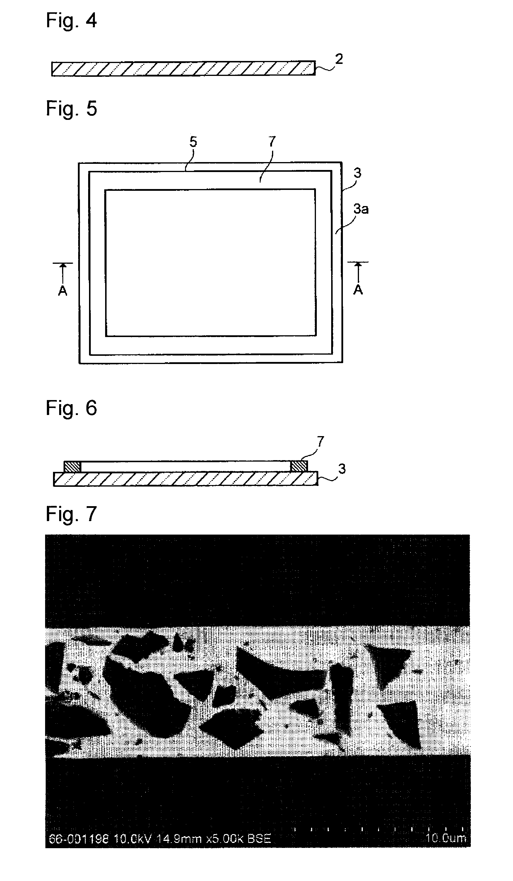
[0091]Formation of a sealing material layer and sealing of the first glass substrate and the second glass substrate together by a laser beam were carried out in the same manner as Example 1 except that a cordierite powder having an average particle size (D50) of 2.6 μm and a specific surface area of 4.5 m2 / g was employed as a low expansion filler. The temperature of the sealing material layer at the time of irradiation of laser beam, was 620° C. in the same manner as in Example 1. The state of an electronic device having a glass panel thus produced, was observed, and as a result, no generation of a crack or a breakage was observed in the glass substrates or the sealing layer, and it was confirmed that these components were satisfactorily sealed together. Further, observation and image analysis of the cross-section of the sealing layer were carried out in the same manner as Example 1, and as a result, the fluidity inhibition value was 1.26 μm−1 and the thermal expansion value was 74×...

example 3

[0092]Formation of the sealing material layer and the sealing of the first glass substrate and the second glass substrate together by a laser beam were carried out in the same manner as in Example 1 except that 74.5 volume % of the bismuth glass frit, 24.5 volume % of the cordierite powder and 1.0 volume % of the laser absorbent were mixed to produce a sealing material (thermal expansion coefficient (50 to 350° C.): 75×10−7 / ° C.). The temperature of the sealing material layer at the time of laser irradiation was 620° C. in the same manner as in Example 1. The state of an electronic device having a glass panel thus produced was observed, and as a result, no formation of a crack or a breakage was observed in the glass substrates or the sealing layer, and it was confirmed that these components were satisfactorily sealed together. Further, observation and image analysis of the cross-section of the sealing layer were carried out in the same manner as Example 1, and as a result, the fluid...


PUM

PropertyMeasurementUnit
Fractionaaaaaaaaaa
Fractionaaaaaaaaaa
Thicknessaaaaaaaaaa

Abstract

Provided is an electronic device wherein at a time of laser-sealing a space between two glass substrates, it is possible to suppress generation of a crack or a breakage etc. in the glass substrates or a sealing layer. When a cross-section of the sealing layer 6 of the electronic device is observed, the sum total of perimeter lengths of the low expansion filler and the laser absorbent present in a unit area (fluidity inhibition value) is from 0.7 to 1.3 μm−1, and the sum total (thermal expansion value) of a value obtained by multiplying the area ratio of the sealing glass by the thermal expansion coefficient, and a value obtained by multiplying the sum total of the area ratios of the low expansion filler and the laser absorbent by the thermal expansion coefficient of the low expansion filler, is from 50 to 90×10−7/° C.

Description

TECHNICAL FIELD[0001]The present invention relates to an electronic device comprising two glass substrates having peripheral portions sealed together and an electronic element portion provided between the substrates.BACKGROUND ART[0002]A flat panel display device (FPD) such as an organic EL display (organic electro-luminescence display: OELD), a field emission display (FED), a plasma display panel (PDP) or a liquid crystal display device (LCD) has such a structure that a glass substrate for element on which a display element is formed and a sealing glass substrate are disposed to face each other and a display element is sealed in a glass package comprising two such glass substrates bonded (refer to Patent Document 1). For a solar cell such as a dye-sensitized solar cell, application of a glass package having a solar cell element (photoelectric conversion element) sealed with two glass substrates has been studied (refer to Patent Documents 2 to 4).[0003]As a sealing material to seal ...

Claims


Application Information

Patent Timeline
IPC IPC(8): C03C27/06
CPCC03C8/04C03C8/24C03C27/06G02F1/1339H01J2211/48Y10T428/239H01J9/261H01J11/48H01J2329/867G02F1/1303H01J2329/8675
Inventor YAMADA, KAZUOONO, MOTOSHIWATANABE, MITSURUTAKEUCHI, TOSHIHIROTAKEDA, SATOSHI
Owner ASAHI GLASS CO LTD
Why Eureka
Try Eureka