Means for controlled sealing of endovascular devices

a technology of endovascular devices and sealing mechanisms, applied in the field of endovascular devices, can solve the problems of life-threatening, severe hemorrhage or other complications, sudden death, and inability of the vessel to conduct fluids, and achieve the effects of preventing leakage, excellent sealing, and eliminating prosthetic-annular incongruen

Inactive Publication Date: 2013-07-25
ENDOLUMINAL SCI
View PDF5 Cites 163 Cited by
  • Summary
  • Abstract
  • Description
  • Claims
  • Application Information

AI Technical Summary

Benefits of technology

[0024]In yet another embodiment, a mechanism enables both deployment and retrieval of the system. This is particularly important from the ease of use and placement accuracy perspective. This feature enables the physician to change/alter the placement of the device in vivo if it was not properly positioned in the first attempt. Also, in the event of some complication during the operation, the physician can completely retrieve the device out of the patient (even after the “expandable material” has completely expande

Problems solved by technology

Aneurysms affect the ability of the vessel to conduct fluids, and can be life threatening if left untreated.
As the size of an aneurysm increases, there is an increased risk of rupture, which can result in severe hemorrhage or other complications including sudden death.
Such procedures, however, can require extensive surgery and recovery time.
Patients often remain hospitalized for several days following the procedure, and can require several months of recovery time.
Moreover, the morbidity and mortality rates associated with such major surgery can be significantly high.
When an endoleak occurs, it can cause continuous pressurization of the aneurysm sac and may result in an increased risk of rupture.
As a result, the left ventricle has to work harder to maintain adequate blood flow through the body.
If left untreated, aortic stenosis can lead to life-threatening problems including heart failure, irregular heart rhythms, cardiac arrest, and chest pain.
However, there is a large pool of patients affected by severe aortic stenosis who are not candidates for open heart valve replacement surgery because they are considered too old (nonagenarians, centenaries) for such an invasive procedure, or because they are also affected by other co-existing conditions that compound their operative risk (lung, et al., Eur Heart J.
Predictors of paravalvular AR included a low baseline left ventricular ejection fraction (LVEF) and inadeq

Method used


Image

  • Means for controlled sealing of endovascular devices
  • Means for controlled sealing of endovascular devices
  • Means for controlled sealing of endovascular devices

Examples


example 1

Preparation of Hydrogel with Rapid Swelling

[0195]Studies to identify hydrogels having substantial swelling in a short time were performed. The main factors that influence swelling of a hydrogel based on polymerisation and cross-linking of synthetic monomers are:

[0196]Type of monomer

[0197]Type of cross-linker

[0198]Concentration of monomer and cross-linker in the gel

[0199]The ratio of monomer to cross-linker

[0200]Acrylic acid polymers are capable of rapid swelling and are regarded as having good biocompatibility. A number of commercially available cross-linkers can be used to crosslink the polymers to form a hydrogel. These include Bis acrylamide, di(ethylene glycol)diacrylate, and poly(ethylene glycol)diacrylate (MW 500 Da).

[0201]Materials and Methods

[0202]Studies were conducted to identify appropriate combinations of acrylic acid concentration, type of cross-linker, concentration of cross-linker and ratio of monomer to cross-linker. The basic composition of the formulations used to ...

example 2

Assessment of Alternative Crosslinkers for Hydrogels

[0212]The principle behind the selected crosslinkers is that rather than having a short cross-linker with only two polymerizable groups, a polyvalent crosslinker e., a long-chain hydrophilic polymer with multiple polymerizable groups) is being used. A much stronger hydrogel is obtained compared to short chain, divalent crosslinkers. While these gels are very firm, they possess very good swelling characteristics. Very strong gels do not normally swell very much.

[0213]Poly vinyl alcohol (PVA) was derivatized with allyl glycidyl ether under alkaline conditions. Gels were made by combing acrylic acid with the PVA-based crosslinker and then polymerizing the mixture by free radical polymerization using ammonium persulfate and TEMED as initiators.

[0214]In principle, the crosslinker can be made with a number of different starting materials: A range of PVAs as well as partially hydrolyzed poly vinyl acetates, 2-hydroxyethyl methacrylates (H...

example 3

Demonstration of Sealing in In Vitro Model

[0221]Materials and Methods

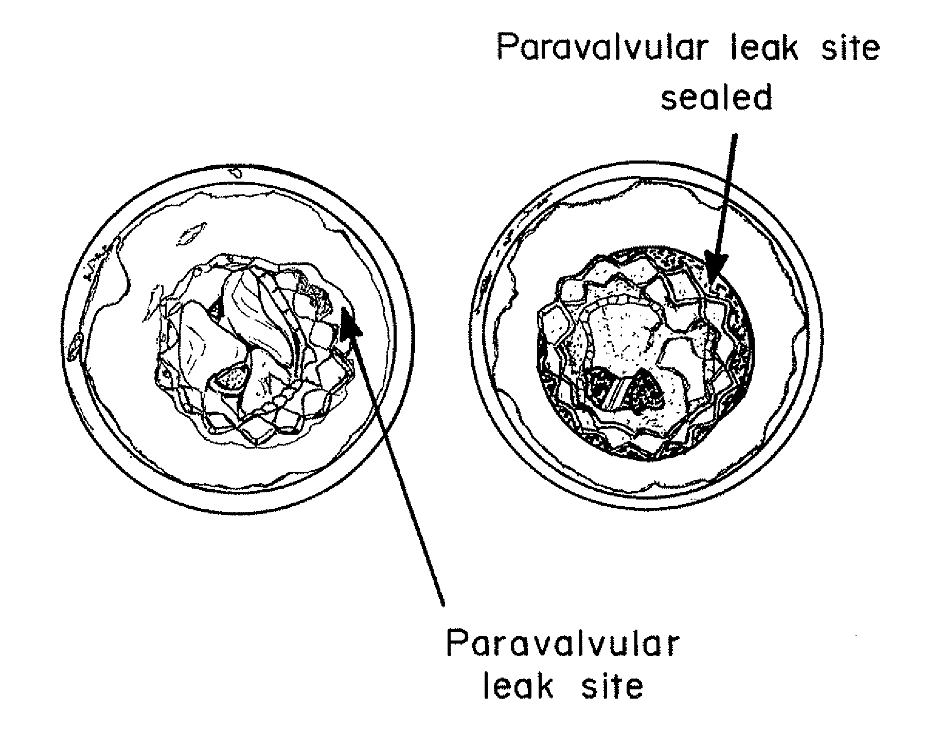
[0222]An in vitro model of a TAV implantation shown in FIGS. 15A-15B was constructed using a tube having placed therein a TAV formed of a collapsible mesh 102 securing heart leaflets 104. In the model the mesh 102 did not seat uniformly into the tube, creating a paravalvular leak site 106 between a region of the mesh 102 and the tube 100.

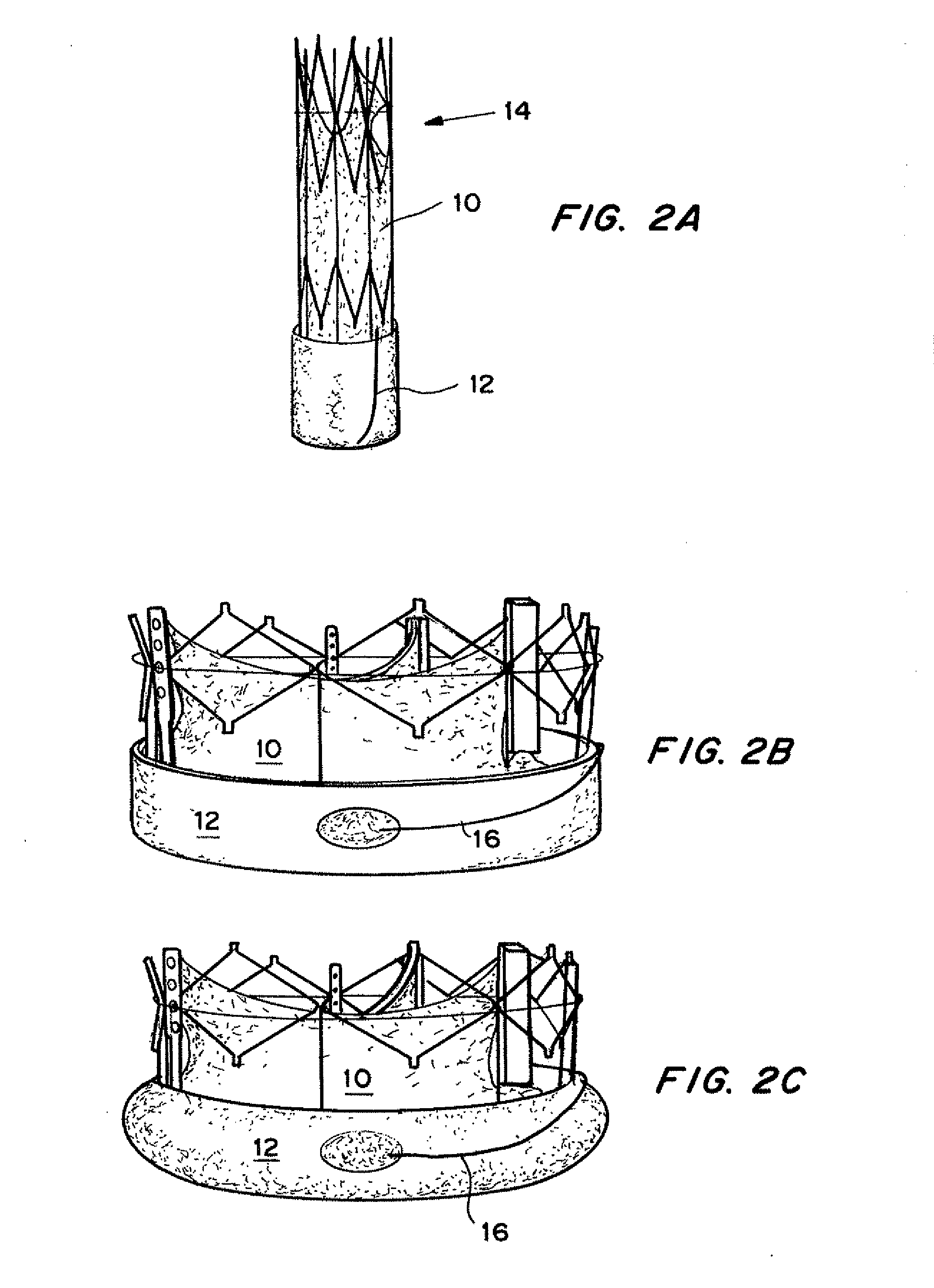
[0223]The TAV includes an expandable seal as described above with reference to FIGS. 2A-2C. The seal 12 was expanded using wire 16 to expose seal 12 to the surrounding fluid (blood), causing the hydrogel to expand and press the seal 12 against the interior of the tube 100, causing the seal 12 membrane to seal the perivalvular leak site 108.

[0224]Results

[0225]FIG. 15A shows a paravalvular leak site 106 due to device inapposition. FIG. 15B shows the leak site is sealed with the seal capsule 108 without disturbing the base geometry of the device. The conformation of the seal happens a...


PUM

PropertyMeasurementUnit
Lengthaaaaaaaaaa
Pore sizeaaaaaaaaaa
Pore sizeaaaaaaaaaa

Abstract

Expandable sealing means for endoluminal devices have been developed for controlled activation. The devices have the benefits of a low profile mechanism (for both self-expanding and balloon-expanding prostheses), contained, not open, release of the material, active conformation to the “leak sites” such that leakage areas are filled without disrupting the physical and functional integrity of the prosthesis, and on-demand, controlled activation, that may not be pressure activated.

Description

CROSS-REFERENCE TO RELATED APPLICATIONS[0001]The present application is a continuation-in-part of U.S. Ser. No. 13 / 476,695, filed May 21, 2012, which claims the benefit of priority to U.S. Ser. No. 61 / 532,814, filed Sep. 9, 2011, both of which are incorporated herein by reference in their entirety.FIELD OF THE INVENTION[0002]The present disclosure is directed generally to endoluminal devices and associated systems and methods, and specifically to a method and devices for controlled actuation of means for sealing of an endoluminal prosthesis to a vessel wall.BACKGROUND OF THE INVENTION[0003]An aneurysm is a localized, blood-filled dilation of a blood vessel caused by disease or weakening of the vessel wall. Aneurysms affect the ability of the vessel to conduct fluids, and can be life threatening if left untreated. Aneurysms most commonly occur in arteries at the base of the brain and in the aorta. As the size of an aneurysm increases, there is an increased risk of rupture, which can ...

Claims


Application Information

Patent Timeline
IPC IPC(8): A61F2/00
CPCA61F2210/0061A61L27/16A61L27/52A61L31/145A61F2/24A61F2/82A61F2/0063A61F2250/0069A61L2430/20A61F2002/823C08L33/08C08L29/04A61F2/2418A61L27/18A61L31/06A61L31/048A61F2250/0003C08L71/02
Inventor MITRA, ASHISH SUDHIRCHONG NG, MARTIN KEANVICTOR WONG, PAK MANBOBILLIER, BEN COLINSOMMER-KNUDSEN, JENS
Owner ENDOLUMINAL SCI
Why Eureka
Try Eureka