Method of drying coating film formed on pet film surface and coating film drying furnace

a coating film and furnace technology, applied in the direction of furnaces, lighting and heating apparatus, manufacturing tools, etc., can solve the problems of reducing productivity and reducing dimension precision in stacking steps, and achieve the effect of preventing temperature rise of pet films, reducing temperature rise, and efficient drying in a short period of tim

Active Publication Date: 2013-08-29
NGK INSULATORS LTD
View PDF9 Cites 6 Cited by
  • Summary
  • Abstract
  • Description
  • Claims
  • Application Information

AI Technical Summary

Benefits of technology

[0012]In the method of drying a coating film formed on a surface of a PET film according to the present invention, an infrared heater having a structure such that an outer circumference of a filament is covered with a protection tube, and a partition wall for forming a flow passageway of a cooling fluid that restrains rise in temperature of a heater surface is provided in a space surrounding this protection tube is used. The infrared heater having this structure can maintain the temperature on the outer surface of the heater to be at a low temperature by means of the cooling fluid despite the fact that the infrared heater can raise the filament temperature and can radiate an infrared ray having a dominant wavelength of 3.5 μm or less. Generally, in an infrared heater, when the filament temperature is raised, the temperature of the protection tube on the outer circumference of the filament also rises, whereby the protection tube on the outer circumference becomes a secondary heating body that radiates an infrared ray of a longer wavelength to raise the temperature within the drying chamber. However, in the present invention, this problem is avoided, so that the temperature rise of the PET film can be prevented.
[0013]Therefore, according to the present invention, the water or organic solvent having an absorption spectrum of 3.5 μm or less can be efficiently dried in a short period of time by radiating an infrared ray having a dominant wavelength of 3.5 μm or less onto the coating film formed on the surface of the PET film without raising the temperature within the drying chamber. Moreover, since the PET film is hardly heated by the infrared ray having a dominant wavelength of 3.5 μm or less, the coating film can be dried without heating the PET film. As a result, there will be no heat shrinkage of the PET film after drying as in a conventional case; therefore, a compression stress is not generated in the dried thin film. Also, since the drying can be carried out while maintaining a low temperature, diffusion of the metal powder used in the MLCC or the like can be prevented; therefore, the method is useful also in a step of multiple-layer stacking of the thin film.
[0014]In particular, when the PET film is dried while being maintained at a temperature lower than its glass transition point, the influence of the heat shrinkage at the time of cooling can be restrained down to a level practically having no problem. For this purpose, it is preferable to perform cooling of the PET film in combination. In particular, when a cooling air is brought into contact with the surface of the PET film on which the coating film has been formed, the evaporated water or the vapor of organic solvent can be quickly discharged to the outside, so that the efficiency of drying can be further enhanced.
[0015]When the coating film formed on the surface of the PET film has a thickness of 100 μm or more, the temperatures of the upper and lower surfaces of the coating film may become nonuniform during the drying step, whereby a strain caused by thermal stress is liable to be generated. In contrast, by first radiating an infrared ray having a dominant wavelength of 3.5 μm or less only from a back surface side of the PET film and subsequently radiating an infrared ray having a dominant wavelength of 3.5 μm or less from a front surface side of the PET film on which the coating film has been formed thereby to dry the coating film as in the invention according to the fourth aspect, energy can be uniformly dispersed into the coating film without drying the coating film at a stage before the start of drying, and the temperature in the film can be made uniform in a state before the start of drying even when the film is formed to have a thickness of 100 μm or more. This allows that a temperature difference is less liable to occur between the upper and lower surfaces of the coating film in the drying process, the thermal stress within the film is reduced, and the phenomenon of generation of strain caused by the thermal stress can be effectively avoided.
[0016]In a coating film drying furnace, when the cooling air feeding nozzles of the floor part are placed at positions that face the infrared heaters of the ceiling part, the cooling air feeding nozzles are heated by absorbing the light radiated from the infrared heaters, which may cause secondary radiation of heat into the furnace. In contrast, when the cooling air feeding nozzles are placed at positions that face gap spaces formed between adjacent infrared heaters in the ceiling part as in the invention according to the fifth aspect, the secondary radiation from the cooling air feeding nozzles can be avoided.

Problems solved by technology

However, by such a conventional method, the base film that has been expanded by being heated during the drying shrinks in the cooling step after the drying, whereby a compression stress is generated in the coating film formed on the surface thereof.
The coating film that has received the compression stress is deformed when peeled off from the base film, thereby causing a problem of decrease in dimension precision in the stacking step.
Also, when the drying temperature is lowered in order to avoid this problem, it will take a long period of time until the drying is completed, thereby leading to decrease in productivity.

Method used


Image

  • Method of drying coating film formed on pet film surface and coating film drying furnace
  • Method of drying coating film formed on pet film surface and coating film drying furnace
  • Method of drying coating film formed on pet film surface and coating film drying furnace

Examples


first embodiment

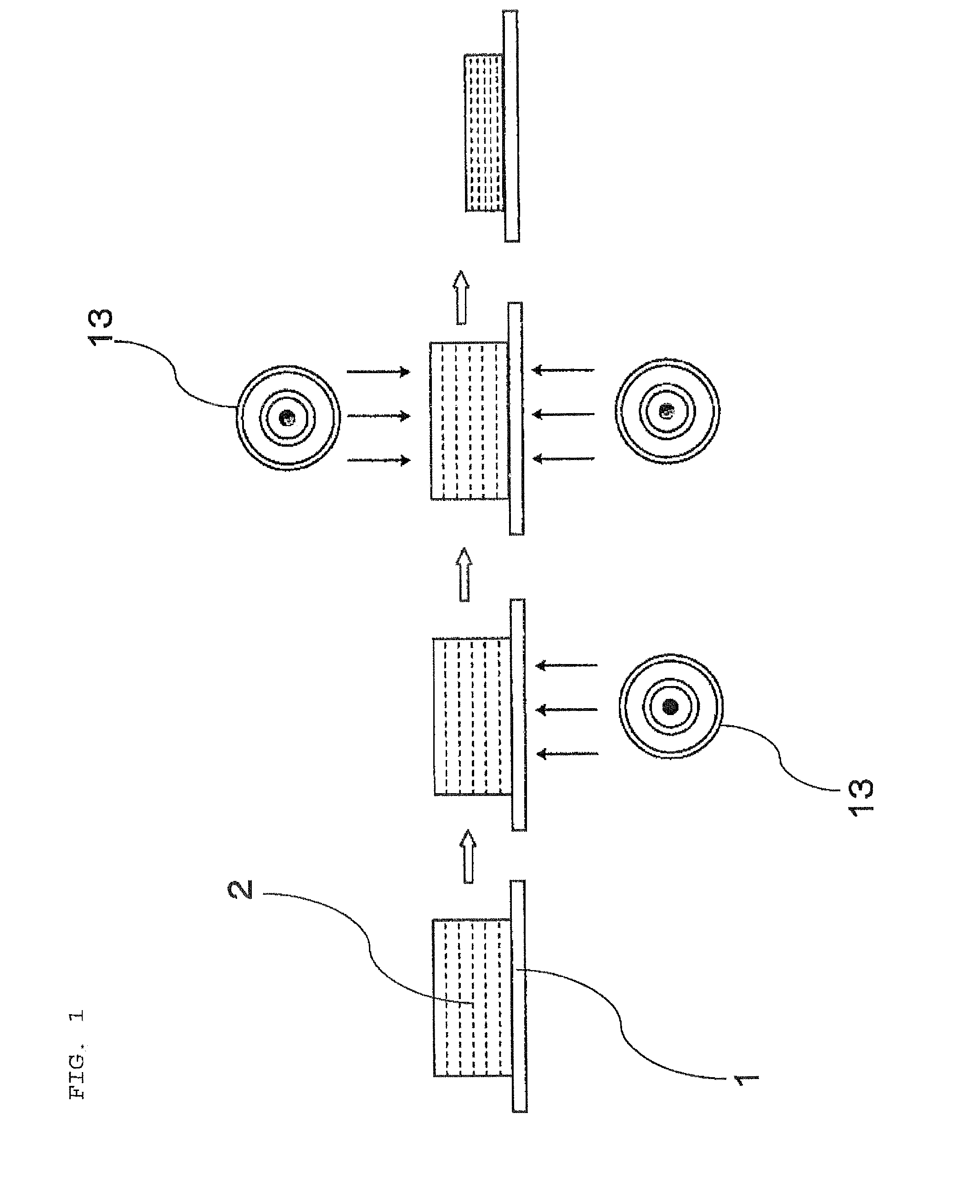
[0023]FIG. 1 is a schematic enlarged cross-sectional view of a coating film. Reference numeral 1 denotes a PET film (polyethylene terephthalate film) which is a base film, and reference numeral 2 denotes a coating film formed on the surface thereof. The coating film 2 of the present embodiment is obtained by dispersing a solute such as a barium titanate powder 3, which is one kind of a ceramic powder, together with an organic binder into an organic solvent. As the organic solvent, terpineol or the like is used. Here, it goes without saying that the kind of these ceramic powder and organic solvent can be changed in accordance with an intended product.

[0024]Generally, water or an organic solvent has an absorption spectrum of 3.5 μm or less and therefore absorbs an infrared ray having a dominant wavelength of 3.5 μm or less to be efficiently heated and evaporated, whereas a PET resin has a physical property of being hardly heated by the infrared ray having a dominant wavelength of 35 μ...

examples

[0043]The coating film drying speed was measured using an experimental furnace in which infrared heaters were disposed in the ceiling part. The base film that was put to use was a PET film having a thickness of 30 μm, and the base film having a slurry applied to a thickness of 80 μm on one surface thereof was dried. This slurry contains barium titanate, which is a ceramic powder, as a solute, and contains NMP as an organic solvent and PVDF (polyvinylidene fluoride) as an organic binder.

[0044]The temperature during the drying was measured with use of a thermocouple thermometer attached to the surface of the coating film, and the drying experiment was carried out by the following two methods under restrictions such that the coating film temperature (which is about the same temperature as the PET film temperature because the coating film is in close adhesion to the PET film) is maintained to be 40° C. or less at all times. In all of the methods, the number N of the test pieces was 2.

[0...

second embodiment

[0048]The present invention is not limited to the above-described embodiment 1 and can be applied to a film of a type having a large film thickness in which the thickness of the coating film is 100 μm to 2 mm. Hereafter, this will be described as embodiment 2. The drying furnace 10 to be used is the same as in the embodiment 1.

[0049]In the embodiment 2, the thickness of the PET film 1 is 10 to 100 μm, and the thickness of the coating film 2 is 100 μm to 2 mm in a state before drying shown on the left side of FIG. 1.

[0050]When the coating film formed on the surface of the PET film has a thickness of 100 μm or more, the temperatures of the upper and lower surfaces of the coating film may become nonuniform during the drying step, whereby a strain caused by thermal stress is liable to be generated. In contrast, in the present embodiment, the coating film is dried by first radiating an infrared ray having a dominant wavelength of 3.5 μm or less only from a back surface side of the PET fi...


PUM

PropertyMeasurementUnit
thicknessaaaaaaaaaa
thicknessaaaaaaaaaa
dominant wavelengthaaaaaaaaaa

Abstract

A method of drying a coating film formed on a surface of a PET film includes radiating an infrared ray having a dominant wavelength of 3.5 μm or less from an infrared heater onto a PET film on whose surface the coating film containing water or an organic solvent having an absorption spectrum of 3.5 μm or less has been formed, where the infrared heater has a structure such that an outer circumference of a filament is covered with a protection tube, and a partition wall for forming a flow passageway of a cooling fluid that restrains rise in temperature of a heater surface is provided in a space surrounding this protection tube, and bringing cooling air into contact with the surface of the PET film / coating film has been formed, so as to dry the PET film at a temperature lower than a glass transition point of the PET film.

Description

FIELD OF THE ART[0001]The present invention relates to a method of drying a coating film formed on a PET film surface and a coating film drying furnace.BACKGROUND ART[0002]In a process of manufacturing an electronic component having a multiple-layer structure such as an MLCC (multiple-layer ceramic capacitor), a chip inductor, or an LTCC (low-temperature co-fired ceramic), a technique of forming a coating film containing a ceramic powder or metal powder, an organic binder, and an organic solvent on a surface of a base film, peeling the coating film off from the base film after drying the film, and stacking the film is adopted, as shown, for example, in JP 07-251411 A. As this base film, a PET film being excellent in strength and inexpensive is widely used.[0003]In order to enhance the productivity of this drying step, an infrared heater or a warm air is generally used as heating means. However, by such a conventional method, the base film that has been expanded by being heated durin...

Claims


Application Information

Patent Timeline
Patent Type & Authority Applications(United States)
IPC IPC(8): F26B3/34
CPCB05D3/0263B05D3/0426B28B1/30F26B3/343B05D7/04C09D5/00
Inventor FUJITA, YUUKIKONDO, YOSHIOAOKI, MICHIRO
Owner NGK INSULATORS LTD
Why Eureka
Try Eureka