Dc-side leakage current reduction for single phase full-bridge power converter/inverter

a technology of dc-side leakage current and power converter, which is applied in the direction of power conversion systems, photovoltaic energy generation, connection, etc., can solve the problems of high leakage current generation, aging of components and apparatus connected to the power converter, and high noise so as to suppress high-frequency emi noise and leakage current, and avoid the generation of low-frequency emi noise

Active Publication Date: 2013-09-12
VIRGINIA TECH INTPROP INC
View PDF15 Cites 45 Cited by
  • Summary
  • Abstract
  • Description
  • Claims
  • Application Information

AI Technical Summary

Benefits of technology

[0010]It is another object of the invention to provide a full-bridge power converter in which low frequency EMI noise and leakage current are reduced to extremely low levels by modified control of the switches forming the full-bridge circuit through use of a feedback circuit, either alone or in addition to suppressing high-frequency EMI noise and leakage current by filtering.
[0011]It is a further object of the invention to provide a modified unipolar modulation (UM) technique which substantially avoids the generation of low frequency EMI noise and corresponding leakage current.
[0012]In order to accomplish these and other objects of the invention, a full-bridge single phase bidirectional AC/DC power converter is provided having two phase legs on an AC side thereof and including a plurality of switches connected in a full bridge configuration, a choke comprising magnetically coupled windings connected in series in respective ones of the two phase legs, a split capacitor connected between the two phase legs, and a connection betw

Problems solved by technology

However, many electrical and electronic devices must operate from a more or less constant voltage and conversion from AC power to direct current (DC) power is required.
However, high frequency switching causes so-called electromagnetic interference (EMI) noise which must be removed by filtering.
Such leakage currents can present a safety issue as well as generating EMI noise and causing aging of components and apparatus connected to the power converter.
Photovoltaic (PV) cells of which solar power generation systems are comprised are particularly subject to damage from leakage currents.
However, if the transformer is operated at the low line frequency, the transformer must be of large size, weight and cost to deliver significant power.
If the transformer is operated at a high switching frequency, more switching devices and conversion stages are required, significantly compromising overall system efficienc

Method used


Image

  • Dc-side leakage current reduction for single phase full-bridge power converter/inverter
  • Dc-side leakage current reduction for single phase full-bridge power converter/inverter
  • Dc-side leakage current reduction for single phase full-bridge power converter/inverter

Examples


Embodiment Construction

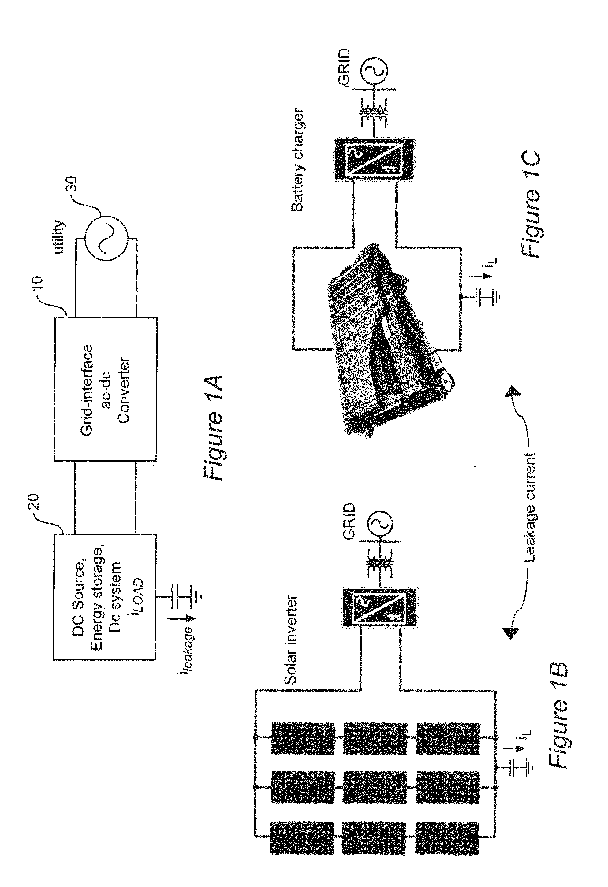
[0031]Referring now to the drawings, and more particularly to FIG. 1A, there is shown a high-level block diagram of a generic configuration of an application of a bi-directional power converter or inverter 10 interfacing between a DC power source, such as a photovoltaic (PV) cell array, as shown in FIG. 1B, or DC energy storage, as shown in FIG. 1C and / or load 20 and an AC power utility or distribution grid 30. As alluded to above, power can be transferred in either direction between DC Source, storage or load 20 and the AC utility or distribution grid 30. For example, DC source, storage and / or load can be a single device such as a PV cell array, a storage battery or an electronic apparatus but could also be a DC distribution system such as a DC nanogrid, as alluded to above, which could include one or more of any of DC power sources, storage devices or loads, in which case, power transferred through converter 10 would be the net difference between power generated and power consumed...


PUM

PropertyMeasurementUnit
Electric potential / voltageaaaaaaaaaa
Frequencyaaaaaaaaaa
Magnetismaaaaaaaaaa

Abstract

Leakage current through stray or parasitic capacitance (which is particularly large in devices such as photovoltaic cell arrays and which are damaged by such leakage currents) due to common mode switching noise in a full bridge single phase power converter is reduced at high frequencies by magnetically coupling the two phase legs on the AC side of the power converter and connecting mid points of the AC and DC sides of the power converter and is reduced at low frequencies by use of a feedback arrangement that modifies sinusoidal modulation of the switches of the full bridge converter to function as an active filter. The magnetic coupling for the two phase legs is designed in a simple manner to avoid saturation based on volt-second considerations.

Description

CROSS-REFERENCE TO RELATED APPLICATIONS[0001]This application claims priority of U. S. Provisional Patent Application Ser. No. 61 / 607,666, filed Mar. 7, 2012, which is hereby incorporated by reference in its entirety.FIELD OF THE INVENTION[0002]The present invention generally relates to power converters and voltage source modules and, more particularly, to bi-directional AC / DC power converters and reduction of leakage current therein.BACKGROUND OF THE INVENTION[0003]At the present time, electrical power is generally generated and distributed as alternating current (AC) power since voltage can be readily changed through use of transformers; allowing very high voltage and relatively low current for power transmission over large distances with reduced ohmic losses. However, many electrical and electronic devices must operate from a more or less constant voltage and conversion from AC power to direct current (DC) power is required. In some cases, it has been found effective to distribut...

Claims


Application Information

Patent Timeline
IPC IPC(8): H02M7/219H02M1/14H05K13/00
CPCH02M7/797Y10T29/49117Y02E10/56H02M2001/123H02M1/123
Inventor DONG, DONGLUO, FANGBOROYEVICH, DUSHANMATTAVELLI, PAOLO
Owner VIRGINIA TECH INTPROP INC
Why Eureka
Try Eureka