Leakage resistance detection device for an on-board high voltage device and leakage resistance detection method therefor

a leakage resistance detection and high voltage technology, applied in the direction of testing circuits, instruments, process and machine control, etc., can solve the problems of deteriorating detection accuracy of monitoring voltage, inability to make ground abnormality determination immediately, and inability to make ground abnormality determination in pulse generation period, etc., to achieve the effect of rapid output of resistance abnormality determination and improved search performan

Active Publication Date: 2013-09-19
MITSUBISHI ELECTRIC CORP
View PDF3 Cites 51 Cited by
  • Summary
  • Abstract
  • Description
  • Claims
  • Application Information

AI Technical Summary

Benefits of technology

[0024]It is a first object of the present invention to provide a leakage resistance detection device, which is capable of variably and easily setting a value of a limit leakage resistance as a setting constant with respect to an arithmetic control circuit, and which is capable of solving the above-mentioned first problem to measure a leakage resistance without waiting for a logic inversion end of a repetitive command signal, to thereby detect the occurrence of ground abnormality quickly.
[0025]Further, it is second and third objects of the present invention to provide a leakage resistance detection device, which is capable of solving the above-mentioned second and third problems to perform accurate measurement of a leakage resistance at the timing of the 1.5th cycle of a repetitive command signal at the latest after a monitoring voltage deviates from a proper range due to an abrupt change in leakage resistance and then returns to the proper range.
[0029]Therefore, such abnormality determination threshold can be variably and easily set as a setting constant with respect to the arithmetic control circuit, and hence it is possible to determine whether the leakage resistance has become equal to or smaller than the limit leakage resistance and also possible to monitor the secular change in leakage resistance. Further, the calculation result of the leakage resistance can be obtained without waiting for the completion of a half cycle of the charge / discharge pulse with respect to the coupling capacitor. In addition, after the monitoring voltage has deviated from the proper voltage range due to an abrupt change in leakage resistance and then returned to the proper voltage range, the measurement of the leakage resistance is performed by a charge / discharge pulse after the half cycle at the latest without needing a plurality of repetitive command signals. As a result, when the ground abnormality has occurred, the resistance abnormality determination output can be generated quickly, and hence there is an effect of improving the search performance on the ground abnormality that temporarily occurs due to vibrations of the vehicle body.

Problems solved by technology

The first problem of this method is that the leakage resistance Rx is calculated at every end of the generated pulse of the repetitive command signal PLS (at every logic change) and hence, even if the deviation voltage is sufficiently high and the leakage resistance is normal at the timing before the end of the generated pulse, ground abnormality determination cannot be made in the pulse generation period.
The second problem of this method is that, as is apparent from FIG. 29, the characteristics curves for the reference time coefficient α0 exceeding 1.54 are concave at the center, and hence even the same threshold voltage coefficient γ has two solutions of the leakage resistance coefficient β and a correct solution cannot be obtained.
When the repetitive command signal PLS is not a high frequency pulse, there is another problem in that the detection accuracy of the monitoring voltage deteriorates because an abrupt change occurs between the monitoring voltage at the end of the previous cycle and the monitoring voltage at the end of the current cycle.
Thus, the ground abnormality determination cannot be made immediately.
This problem is caused because the coupling capacitor 51 is alternately charged and discharged by the repetitive command signal PLS and hence the next charge starts before the completion of the previous discharge, and the monitoring voltage Vx does not increase or decrease monotonously.
The third problem of the above-mentioned method relates to the above-mentioned second problem and is that, in a transient delay period from when the monitoring voltage Vx returns to the proper range after the abrupt change in leakage resistance Rx to when a plurality of repetitive command signals PLS are operated to enable the measurement of the leakage resistance Rx, the measured value of the deviation voltage Vx2−Vx1 is smaller than that in the stable state used as the determination condition.
Therefore, the obtained leakage resistance coefficient β is a small value, and it may be erroneously determined that ground abnormality has occurred.
Thus, a standby time for avoiding such erroneous determination becomes longer.

Method used


Image

  • Leakage resistance detection device for an on-board high voltage device and leakage resistance detection method therefor
  • Leakage resistance detection device for an on-board high voltage device and leakage resistance detection method therefor
  • Leakage resistance detection device for an on-board high voltage device and leakage resistance detection method therefor

Examples


first embodiment

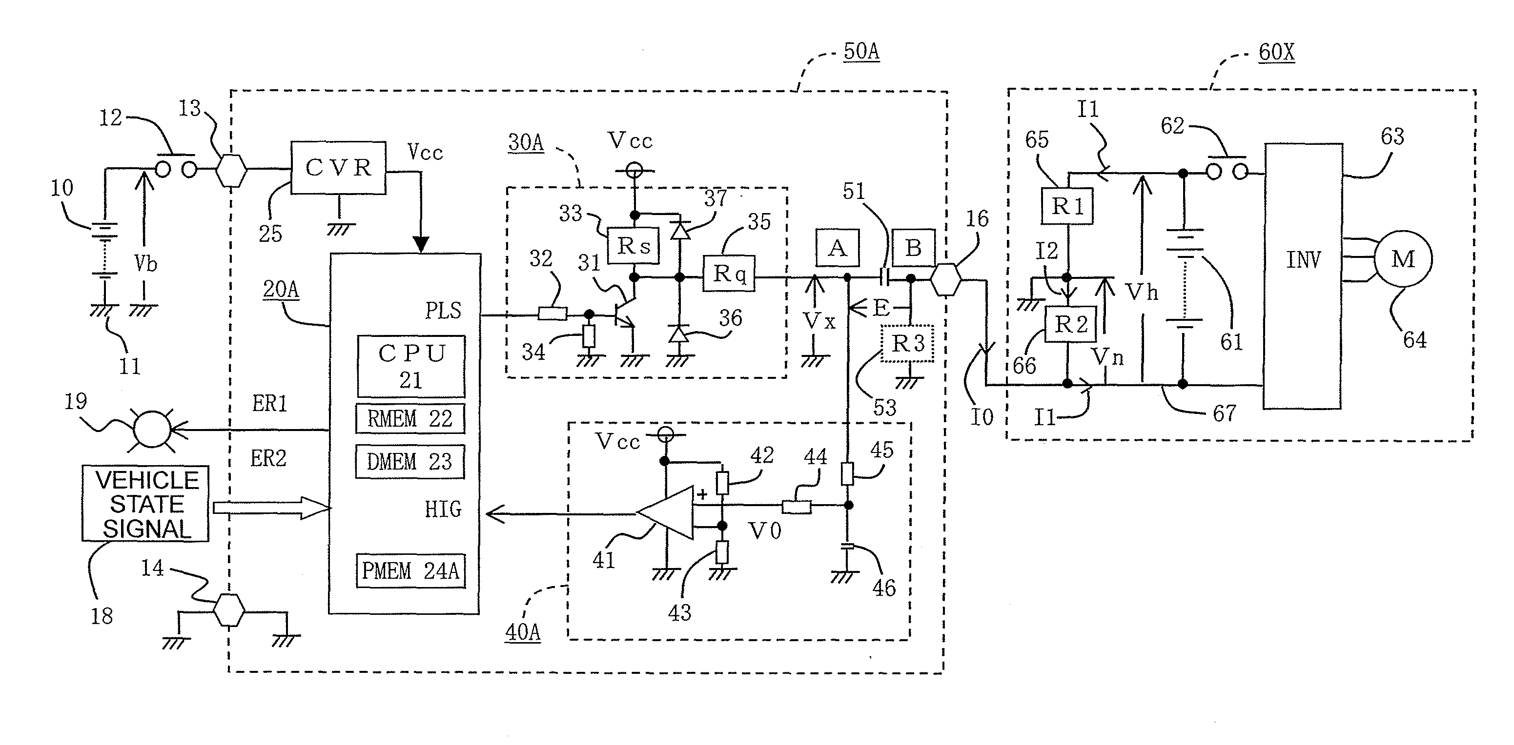
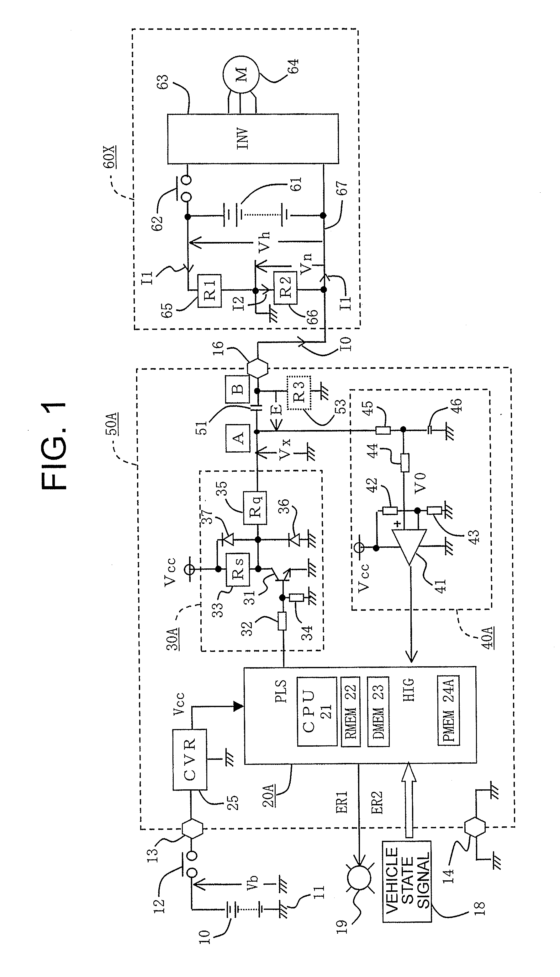
[0061]Now, a description is given with reference to an overall configuration diagram of FIG. 1 illustrating a device according to a first embodiment of the present invention. In FIG. 1, a low voltage DC power source 10, which is externally connected to a leakage resistance detection device 50A, is an on-board battery such as a 12-V secondary lead battery. The low voltage DC power source 10 has a negative terminal grounded to a vehicle body 11. A positive terminal thereof supplies a first power supply voltage Vb via a low voltage power supply switch 12 to a positive-side low voltage power supply terminal 13 provided to the leakage resistance detection device 50A. The low voltage power supply switch 12 uses an output contact of an electromagnetic relay which is energized when a manual power supply switch (not shown) is closed. When the manual power supply switch is opened, the low voltage power supply switch 12 is opened after a short delay time so as to perform delayed feeding.

[0062]...

second embodiment

[0183]Referring to FIG. 8 which is an overall configuration diagram of a device according to a second embodiment of the present invention, the differences from FIG. 1 are mainly described below. In the drawings, the same reference symbols denote the same or equivalent parts. In FIG. 8, a leakage resistance detection device 50B includes an arithmetic control circuit 20B, a repetitive signal output circuit 30B, and a monitoring signal processing circuit 40B, and detects a leakage resistance of an on-board high voltage device 60Y.

[0184]The first main difference is that, in the on-board high voltage device 60Y, a positive-side power supply line 68 is connected to one terminal B of the coupling capacitor 51 via the interconnection terminal 16, and the positive-side equivalent leakage resistor 65 has an equivalent leakage resistance R2 on the interconnection side while the negative-side equivalent leakage resistor 66 has an equivalent leakage resistance R1 on the non-interconnection side....

third embodiment

[0252]Referring to FIG. 12 which is an overall configuration diagram of a device according to a third embodiment of the present invention, the differences from FIG. 1 are mainly described below. In the drawings, the same reference symbols denote the same or equivalent parts. In FIG. 12, a leakage resistance detection device 50C includes an arithmetic control circuit 20C, a repetitive signal output circuit 30C, and a monitoring signal processing circuit 40C, and detects a leakage resistance of an on-board high voltage device 60X.

[0253]The first main difference is that the repetitive signal output circuit 30C includes a charge / discharge switching element 31 such as a PNP transistor, and when the output logic level of the repetitive command signal PLS is “H”, an auxiliary switching element 31a becomes conductive via an auxiliary drive resistor 32a so that the charge / discharge switching element 31 becomes conductive via the drive resistor 32, and when the output logic level of the repet...


PUM


Abstract

The leakage resistance detection device includes a coupling capacitor having one terminal connected to an on-board high voltage device and another terminal connected to a repetitive signal output circuit, and measures a leakage resistance as a function of a transition time during which a monitoring voltage, which is a potential at the another terminal of the coupling capacitor to be charged / discharged in response to an operation of a charge / discharge switching element that operates in response to a repetitive pulse signal, changes from one predetermined voltage to reach another predetermined voltage. When the measured leakage resistance has become equal to or smaller than a predetermined limit leakage resistance, the leakage resistance detection device generates a resistance abnormality determination output.

Description

BACKGROUND OF THE INVENTION[0001]1. Field of the Invention[0002]The present invention relates to a leakage resistance detection device for an on-board high voltage device, which is connectable to an on-board high voltage device including an on-board high voltage DC power source and a high voltage electric load to be fed and driven by the high voltage DC power source and which measures a leakage resistance with respect to a vehicle body as typified by equivalent leakage resistances on the positive and negative potential sides of the on-board high voltage device, so as to inform the abnormality when the leakage resistance reduces, and also relates to a leakage resistance detection method for the on-board high voltage device.[0003]2. Description of the Related Art[0004]In general, an electric car, a hybrid electric car, and other such vehicles use a combination of a DC 12-V low voltage battery and a high voltage battery such as a DC 400-V battery pack, for example. A negative terminal ...

Claims


Application Information

Patent Timeline
Patent Type & Authority Applications(United States)
IPC IPC(8): G06F7/00G01R31/14
CPCG01R27/18Y02T10/7005Y02T10/642B60L3/0069B60L3/12B60L11/1803Y02T10/7275B60L2240/421B60L2240/547B60L2240/80B60L2250/10B60L2250/16B60L2270/145B60L15/20Y02T10/72B60L50/51Y02T10/64Y02T10/70
Inventor NISHIDA, MITSUNORIZUSHI, YUJIYASUKAWA, KOUICHI
Owner MITSUBISHI ELECTRIC CORP
Why Eureka
Try Eureka