However, when images are formed at high speed,
image quality deteriorates.
There are various causes for the quality deterioration of images due to high-speed
image formation.
Among them, defective fixing during a fixing process is the most significant cause.
However, when
system speed increases, the fixing period decreases and unfixed toner images do not obtain sufficient heat during the fixing process; as a result, defective fixing occurs, and final toner images turn out with rough surfaces and a residual image phenomenon called cold offset occurs, thus providing poor images.
It becomes difficult to save energy and increase speed at the same time and a toner that can be sufficiently fixed at a lower temperature is demanded.
However, such a toner is low in heat-resistant storage stability and offset resistance and also has soft toner particles, so that the toner is stressed in forming images at high speed and fixes to the surface of a developing sleeve, thus
staining the sleeve.
Accordingly, when the developing sleeve is stained, the potential of a developer or the like changes, which often causes
ghosting (phenomenon of repeating a preceding image history onto the following image).
However,
ghosting in these systems results from different mechanical causes.
As described above, ghost images in
hybrid development are caused since it is difficult to repeatedly coat toner to make toner amounts even at sections where the toner is developed and is not left on the developing sleeve, and at sections where the toner is not developed and is still left on the developing sleeve in the process of transferring the toner from the developer transfer roller onto the developing sleeve, and thus toner amounts on the developing sleeve during the process of printing following images change on the basis of the history of the preceding image.
However, this method intends to prevent an increase in
electric charge amount that is caused by dragging a developer around with a developing sleeve and repeatedly brushing the developer with the developing sleeve, and is not an
effective method for the two-component developing
system.
Also, as it is mentioned that “in general, when the charging property of a
surface layer is increased, images become darker” herein, this concerns the one-component developing system and is not an
effective solution for residual images in the two-component developing system.
However, since the unevenness on the outer surface is extremely fine, it is gradually ground with a developer or the like, so that the unevenness is ground and the sand-blasted developing sleeve is flattened as the number of prints increases and changes with time.
Accordingly, there is a problem in that the sand-blasted developing sleeve will gradually convey less developer and formed images will be thinner gradually.
Thus, the sand-blasted developing sleeve has a durability issue.
Although it is possible to provide a developing sleeve made of a super-hard stainless steel or to treat the surface of a sleeve to be hard, it is undesirable as the cost increases.
Thus, the pulverized toner is likely to
stain the surface of a developing sleeve and generate ghost images.
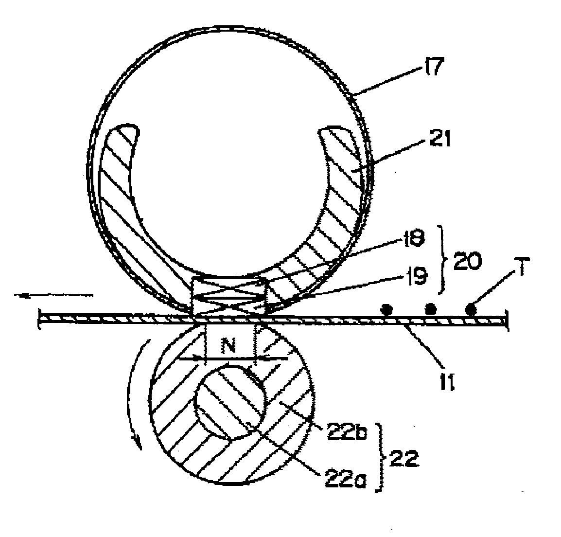
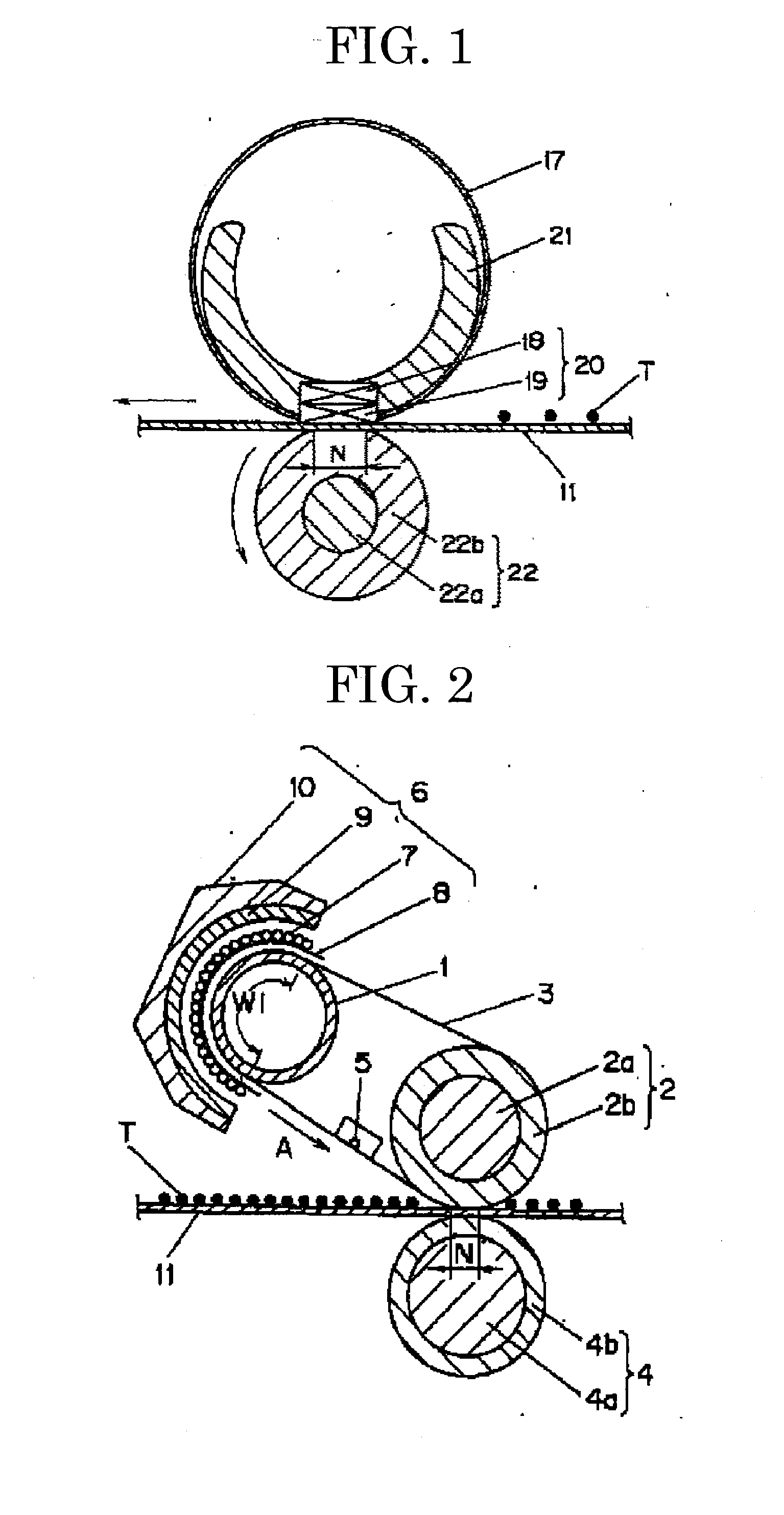
However, since the fixing belt having a small thermal capacity is used in the image forming apparatus, a belt temperature rapidly decreases and fixing properties cannot be sufficiently maintained if images with a large toner amount are formed, and a particular problem called cold offset occurs.
However, lowering Tg in the resin causes the deterioration of
heat resistant storage stability.
Also, when the
softening temperature (T½) decreases due to low-molecular-weight resin or the like, problems such as hot-offset will be found.
Thus, a toner with a good lower-temperature fixing property,
heat resistant storage stability, and hot-offset resistance cannot be obtained just by controlling the thermal characteristics of resin itself.
However, this proposal is not optimal to molecular structures and molecular
mass.
However, the toner in which the crystalline
polyester is used as described in JP-B No. 2931899, has a low
acid value and
hydroxyl value at 5 mgKOH / g or less and at 20 mgKOH / g or less, respectively, and an affinity between paper and the crystalline
polyester is low, so that the toner does not have a sufficient lower-temperature fixing property.
Moreover, the toner in which the crystalline polyester is used as described in JP-A No. 2001-222138, is not optimized for the molecular weight of the toner as a final product and for the existing conditions of the crystalline polyester.
Therefore, the toner containing the crystalline polyester described in JP-A No. 2001-222138 does not necessarily achieve an excellent lower-temperature fixing property and
heat resistant storage stability that are attributed to the crystalline polyester, when it is used as an actual toner.
Also, there is no measurement for hot-offset resistance, so that a temperature width that allows preferable image fixation, may not be maintained.
However, in the attempt to maintain the sea-island phase separation structure of the crystalline
polyester resin in this technique, the dispersion particle size of the crystalline
polyester resin becomes so large that heat resistant storage stability becomes troublesome and electrical resistance becomes too low, generating defective transfer during the transfer process and often causing rough final images.
Thus, a lower-temperature fixing property relies on the crystalline
polyester resin, so that the amount of crystalline polyester resin to be used inevitably increases and the risk of deteriorating heat resistant storage stability becomes high due to the compatibility with the non-crystalline resin.
However, since an extremely large amount of the crystalline polyester resin is used in this art, there is a risk of degrading heat resistant storage stability due to compatibility with a non-crystalline resin.
However, since a crystalline polyester resin is not used in this proposal, a lower-temperature fixing property becomes incomplete, compared with the case where a crystalline polyester resin is used.
This toner has finer
copolymer particles so as to increase the scattering thereof, but the particles have a low compatibility with the binding resin and sharp-melting characteristics decrease because of the
copolymer particles.
However, since the toner does not contain a crystalline polyester, sharp-melting characteristics are insignificant.
However, there is currently no such toner that is fixable by the fixing apparatus described in JP-A Nos. 2005-173445 and 2005-173446 and has sharp-melting characteristics, and good heat resistant storage stability and hot-offset resistance.
