Sintered oxide material, method for manufacturing same, sputtering target, oxide transparent electrically conductive film, method for manufacturing same, and solar cell

a technology of oxide material and oxide, which is applied in the direction of conductive materials, final product manufacture, textiles and papermaking, etc., can solve the problems of insufficient reliability, low reliability, and nothing is mentioned regarding optical transparency in the infrared region or reliability, and achieve excellent optical transparency, excellent durability, and minimize anomalous discharge during sputtering

Active Publication Date: 2013-10-24
TOSOH CORP
View PDF5 Cites 6 Cited by
  • Summary
  • Abstract
  • Description
  • Claims
  • Application Information

AI Technical Summary

Benefits of technology

[0034]The oxide sintered compact of the invention may be suitably used as a sputtering target. By using the sputtering target for sputtering, it is possible to produce an oxide transparent conductive film, while minimizing anomalous discharge during sputtering. The oxide transparent conductive film has excellent optical transparency in the visible light region and the infrared region, and excellent durability. Therefore, when it is used in a solar cell, for example, it can utilize sunlight energy in the infrared region in a highly efficient manner, which has not been possible in the prior art. It is thus possible to provide a solar cell with high photoelectric conversion efficiency.
[0035]The solar cell of the invention has high photoelectric conversion efficiency. The term “solar cell”, as used herein, includes solar cells that employ oxide transparent conductive films, such as silicon-based solar cells employing single crystal silicon, polycrystalline silicon and amorphous silicon, compound-based solar cells such as CuInSe2, Cu(In, Ga)Se2, GaAs and CdTe, and dye-sensitized solar cells.
[0036]An oxide transparent conductive film to be used in a solar cell of the invention exhibits excellent optical transparency even when formed at low temperatures of up to 200° C. In addition, the oxide transparent conductive film has low thickness-dependence for its durability, and can be adjusted to any desired resistance, transmittance and durability. It is therefore possible to effectively direct sunlight to the photoelectric conversion layer of the solar cell. The oxide transparent conductive film also has a strong effect of preventing reduction in the fill factor of the solar cell, and the photoelectric conversion efficiency is therefore extremely high. It is thus possible to obtain a solar cell with high heat-proof humidity resistance.

Problems solved by technology

While measures have been taken to reduce tin content of ITO films in order to satisfy this need, this strategy has tended to result in lower reliability.
ITiO films that have titanium added instead of tin can improve optical transparency in the infrared region, but their reliability is inadequate.
However, nothing is mentioned regarding optical transparency in the infrared region or reliability, which are important for use in solar cells where optical transparency is important.
While this is considered to be a very important issue, no disclosure is provided regarding anomalous discharge during sputtering.
Specifically, with a conventional sputtering target to be used for film formation, it has been difficult to adequately reduce generation of anomalous discharge during sputtering.
This results in the problem of reduction in yield due to particle fly-off during anomalous discharge, and lower productivity.
For thin-film solar cells, the most important issue is to achieve high photoelectric conversion efficiency and high heat-proof humidity resistance.
However, tin-added indium oxide films have high carrier-caused reflection in the near-infrared region, and hence low transmittance.
For this reason, they cannot efficiently utilize sunlight across a wide wavelength range, and their low photoelectric conversion efficiency has been a problem.

Method used


Image

  • Sintered oxide material, method for manufacturing same, sputtering target, oxide transparent electrically conductive film, method for manufacturing same, and solar cell
  • Sintered oxide material, method for manufacturing same, sputtering target, oxide transparent electrically conductive film, method for manufacturing same, and solar cell
  • Sintered oxide material, method for manufacturing same, sputtering target, oxide transparent electrically conductive film, method for manufacturing same, and solar cell

Examples


example 1

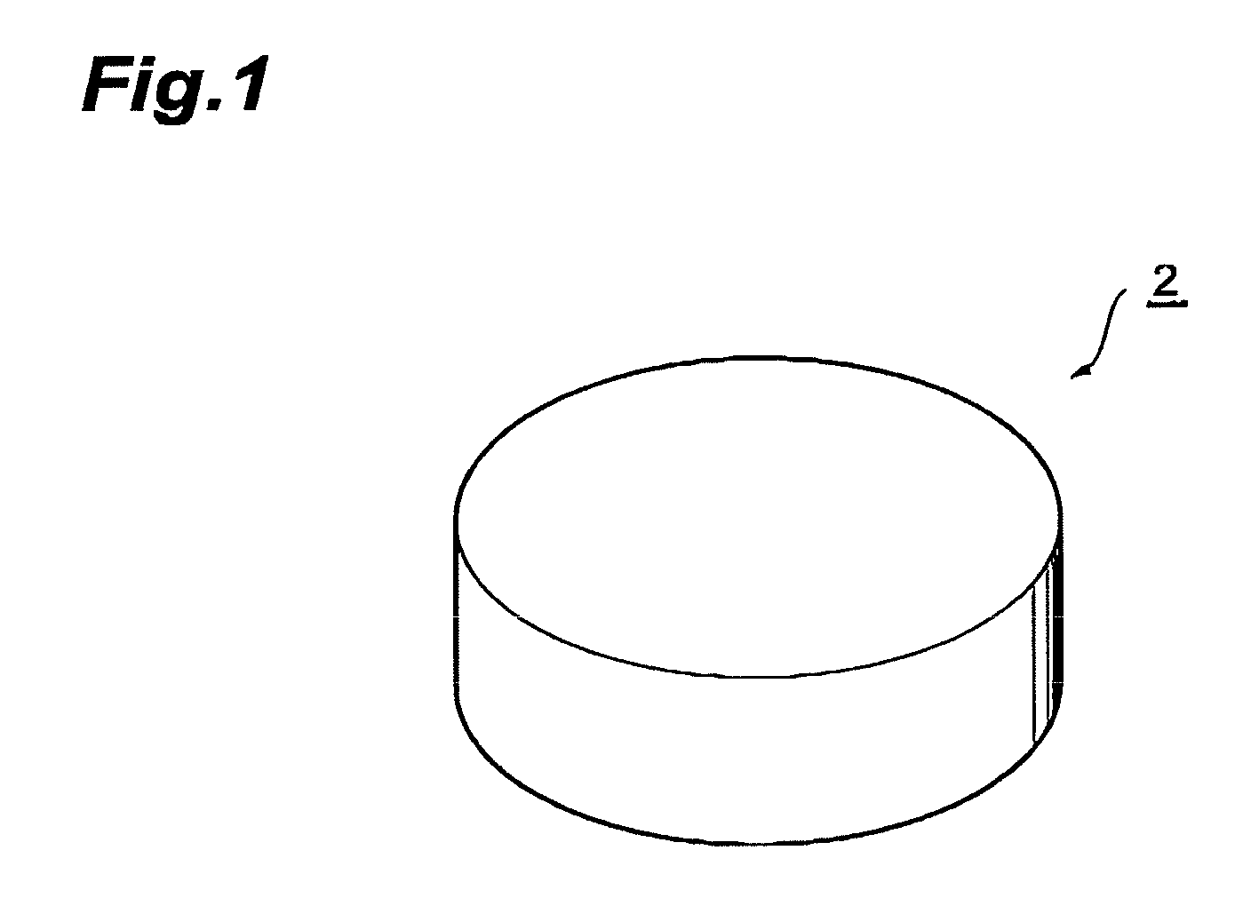
(Fabrication of Oxide Sintered Compact)

[0166]The starting powders used were indium oxide powder with a purity of 99.99 mass % and a mean particle size of 0.5 μm, tin oxide powder with a purity of 99.99 mass % and a mean particle size of 0.5 μm, and strontium carbonate powder with a purity of 99.9 mass % and a mean particle size of 1 μm. The tin oxide powder and the strontium carbonate powder were mixed with a dry ball mill so that the tin, element and the strontium element mixing ratios (based on atomic percent) were the same [Sn / (Sn+Sr)=0.5], to prepare a mixed powder. The mixed powder was calcined in air at 1000° C. for 2 hours and then treated with a dry ball mill to obtain a calcined powder with a mean particle size of 0.2 μm.

[0167]The indium oxide powder and the tin oxide powder were combined with this calcined powder as listed in the “Final powder composition” column in Table 1 and mixed with a dry ball mill. The mean particle size of the mixed powder was 0.2 μm. The obtained ...

examples 2 to 13

[0187]Oxide sintered compacts and oxide transparent conductive films for Examples 2 to 13 were fabricated in the same manner as Example 1, except that the amounts of the indium oxide powder and the tin oxide powder added to the calcined powder obtained in the same manner as Example 1 were varied as shown in the “Final powder composition” column in Table 1.

[0188]The oxide sintered compacts of Examples 2 to 13 were pulverized, and the produced phases were identified in the same manner as Example 1 by an X-ray diffraction test. As a result, in Examples 2 to 4, 6, 7, 9, 10, 12 and 13, only diffraction peaks for a bixbite-type oxide phase and perovskite-type oxide phase were detected, while no diffraction peak for a tin oxide phase or strontium oxide phase was detected. On the other hand, in Examples 5, 8 and 11, only a diffraction peak for a bixbite-type oxide phase was detected, while no diffraction peak for a tin oxide phase or strontium oxide phase was detected.

[0189]Analysis was als...

examples 14 to 18

[0192]Calcined powders were obtained in the same manner as Example 1. An oxide sintered compact and oxide transparent conductive film for Example 14 were fabricated in the same manner as Example 1, except that the amounts of the indium oxide powder and the tin oxide powder added to the calcined powder were varied as shown in the “Final powder composition” column in Table 1, and the firing temperature was changed from 1500° C. to 1400° C.

[0193]An oxide sintered compact and oxide transparent conductive film for Example 15 were fabricated in the same manner as Example 1, except that the amounts of the indium oxide powder and the tin oxide powder added to the calcined powder were varied as shown in the “Final powder composition” column in Table 1, and the firing temperature was changed from 1500° C. to 1350° C.

[0194]An oxide sintered compact and an oxide transparent conductive film for Example 16 were fabricated in the same manner as Example 1, except that the amounts of the indium oxid...


PUM

PropertyMeasurementUnit
particle sizeaaaaaaaaaa
resistivityaaaaaaaaaa

Abstract

The invention provides an oxide sintered compact 2 composed of a crystal phase which consists of a bixbite-type oxide phase and a perovskite-type oxide phase, or a bixbite-type oxide phase, the crystal phase having indium, tin, strontium and oxygen as the constituent elements, and the indium, the tin and the strontium contents satisfying formulas (1) and (2) in terms of atomic ratio, as well as a sputtering target. There are further provided an oxide transparent conductive film formed using the sputtering target, and a solar cell.
Sn/(In+Sn+Sr)=0.01-0.11  (1)
Sr/(In+Sn+Sr)=0.0005-0.004  (2)
[In formulas (1) and (2), In, Sn and Sr represent indium, tin and strontium contents (atomic percent), respectively.]

Description

TECHNICAL FIELD[0001]The present invention relates to an oxide sintered compact, to a method for manufacturing the same, to a sputtering target, to an oxide transparent conductive film, to a method for manufacturing the same, and to a solar cell.BACKGROUND ART[0002]Oxide transparent conductive films have low resistance and high transmittance in the visible light region, and are used as display devices such as liquid crystals, and light receiving elements such as solar cells. Among oxide transparent conductive films, indium oxide films are widely used as tin-added ITO films or zinc-added IZO films.[0003]When utilizing an oxide transparent conductive film for a solar cell, where it is important to have optical transparency across a wide wavelength range, it is desirable to further improve the optical transparency not only in the visible light region but also in the infrared region. While measures have been taken to reduce tin content of ITO films in order to satisfy this need, this st...

Claims


Application Information

Patent Timeline
Patent Type & Authority Applications(United States)
IPC IPC(8): C23C14/08H01L31/0224C23C14/34
CPCC23C14/08C23C14/3407H01L31/022425H01L31/022466C01G19/006C01P2002/34C01P2004/62C01P2006/40C01P2006/60C04B35/01C04B35/457C04B2235/3213C04B2235/3286C04B2235/3293C04B2235/5409C04B2235/5445C04B2235/604C04B2235/77C04B2235/786C23C14/086C23C14/3414C23C14/35H01B1/08C01P2002/50H01L31/022475H01L31/0749C04B35/62635C04B35/62675C04B35/62685C04B35/645C04B2235/6562C04B2235/6565C04B2235/6585C04B2235/6586C04B2235/76C04B2235/768C04B2235/80C04B2235/963Y02E10/541H01L31/1884Y02P70/50C04B35/00C04B35/453C04B35/6261C23C14/34
Inventor KURAMOCHI, HIDETOMATSUMARU, KEITAROAKIIKE, RYOUTSUMI, KENTAROSHIBUTAMI, TETSUO
Owner TOSOH CORP
Why Eureka
Try Eureka