Non-Clogging Airless Spray for High Viscosity, High Surface Tension Fluids

Inactive Publication Date: 2013-12-05
DEVICEGENERICS
View PDF1 Cites 21 Cited by
  • Summary
  • Abstract
  • Description
  • Claims
  • Application Information

AI Technical Summary

Benefits of technology

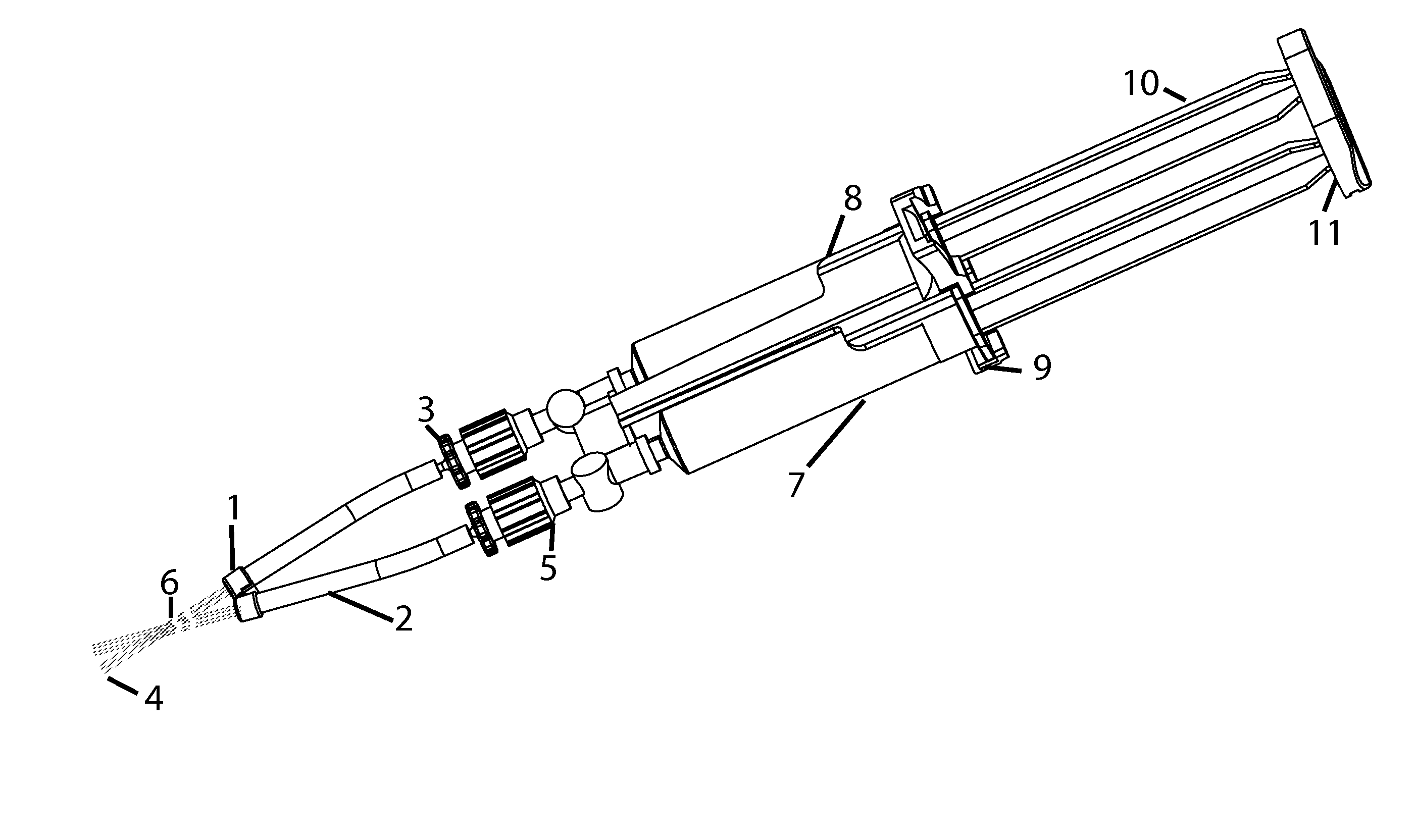
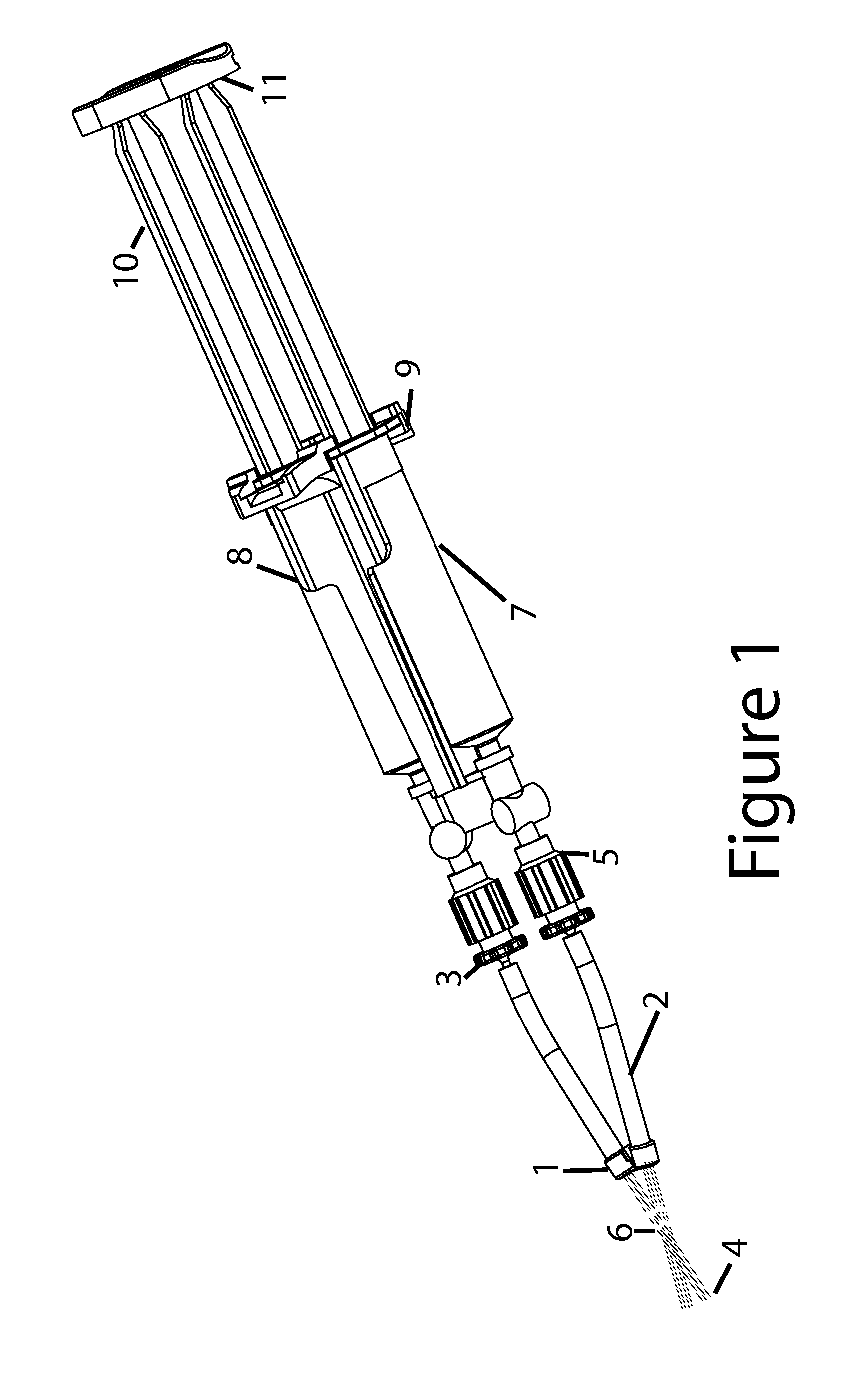
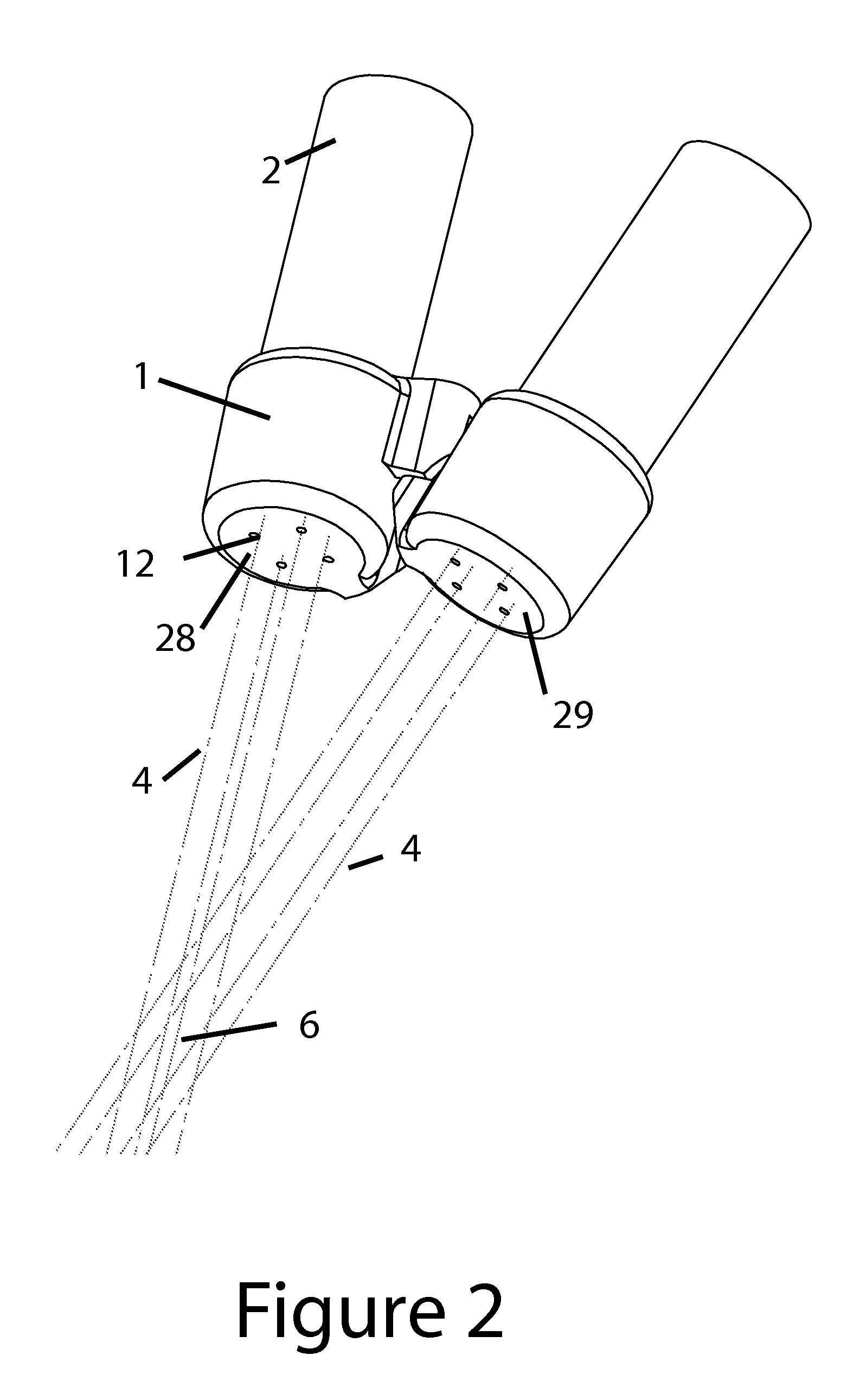
[0034]The invention is intended to dispense biological agents such as fibrin components onto a bleeding surface without the need for an external compressed air or any external energy source. The invention is designed to allow the user to dispense the two liquids comfortably with one hand. The invention comprises a dual syringe device containing the first and second liquids, a spray tip having a proximal and distal end.

Problems solved by technology

Bleeding is a common problem during many types of surgeries.
Some bleeding problems do not lend themselves to cautery or sponges.
If bleeding is coming from an anastomosis site (joining of two vessels such as bypassing an artery around a blockage during open heart surgery), it is not practical to apply electrocautery to these delicate arteries.
Packing sponges around the wound may not be practical; the beating heart for example may dislodge sponges packed around a bypassed artery.
During surgery on the kidney to remove a tumor, a relatively large surface area may be cut away and bleed.
Blood with anti-coagulants can be difficult to control and fibrin sealants may help control bleeding in these applications.
Dripping is simple but may be less desirable in some instances than spraying.
This can be a challenge when the two liquids drip from the dispensing catheter.
Another problem with dripping the two solutions is that the two solutions may combine at the tip and quickly clot prior to reaching the bleeding site.
This problem of premature clotting clogs the tips of these dispensing applicators.
Clogged tips in applicators may be cut away to reopen the two passages in a plastic cannula but this extra step slows the delivery of the hemostatic agent.
The drawback to using air driven spray systems is the added complexity of bringing a compressed air source to the sterile surgical site.
However if unexpected bleeding occurs, prepping the sealant and preparing the air regulator may be more time and effort than is desired by the surgeon.
An additional safety risk with air driven spray systems is the risk of life threatening air embolism.
FDA received complaints that the use of the spray device at higher than recommended pressures and in close proximity to the surface of the tissue could result in air being introduced into a blood vessel.
These accelerants are not practical with sprays involving biological agents to stop bleeding in people.
The regulatory pathway required to qualify spraying biological agents using a synthetic accelerant would be prohibitively long and expensive.
However a two part, high viscosity airless spray poses multiple challenges.
A second problem with airless spraying two component liquids is the difficulty in getting the viscous materials to form a spray pattern without the assist of air

Method used


Image

  • Non-Clogging Airless Spray for High Viscosity, High Surface Tension Fluids
  • Non-Clogging Airless Spray for High Viscosity, High Surface Tension Fluids
  • Non-Clogging Airless Spray for High Viscosity, High Surface Tension Fluids

Examples


Example

[0049]A second embodiment of the invention is shown in FIG. 6. In this embodiment, a radius 19 is applied to the exit hole 20. As opposed to FIG. 3 in which a chamfer is included on the inside of the cap, in FIG. 6, the radius is applied to the outside of the cap. The advantage of this design is that it create a dispersive spray in which the fluid streams flow away from each other and thereby create a wider spray pattern. A second advantage to the design is that this hole configuration creates an artificially smaller hole diameter and thereby creates a much higher exit velocity. As shown in FIG. 6, the biological fluid in each cap form streamlines of fluid flow. In FIG. 6, the streamlines are illustrated as items 22. The streamlines 22 are forced into one of the exit holes which are located to the outer edge of the inner surface of the tubing 2. Locating the holes as far away from the centerline of the tubing, will increase the distance between holes and thereby prevent the exiting ...

Example

[0050]A third embodiment of the design is to combine the two tubes (connecting pieces) 2 into one dual lumen tube which is terminated by one molded spray cap 1. By leaving a slight gap between the end of the cut dual lumen tube and the spray holes, the two liquids may combine and create more homogenous fluid mixture. This third embodiment may improve the mixing of the two fluids at the expense of causing more frequent clogging of the caps.

Example

[0051]A fourth embodiment of the design is illustrated in FIG. 7 and FIG. 8. In this case the exit holes 32 are drilled in a thin plastic film 33 which is bonded to the two connecting pieces 2. The plastic caps 1 described in FIGS. 1-6 are replaced by a single thin film 33. The plastic film 33 is angled via thermoforming or injection molding to form a controlled angle theta which ranges between 160 degrees and 180 degrees. This angle theta creates an included angle between face 30 and face 31. This embodiments allows very small holes (32 creates an improved shower pattern and promotes better mixing of the two fluids. However laser drilling of the exit holes requires relatively thin substrates 33. The ideal thickness of a substrate should be less than 0.015 inch and ideally the thickness of the substrate 33 is between 0.005 and 0.010 inch. This thin section becomes very difficult to injection mold but may be extruded or cast into a thin film. The substrate 33 can be adhesively bonded...


PUM


Abstract

The invention describes a dispensing spray device coupled to a dual syringe device whose outlets terminate in a plurality of small holes of sufficient small size to induce high velocity jets in the fluid exiting each of the holes. The holes in two caps are forced into orientation with respect to each other at an angle governed by the included angle of the two caps. The two fluids exit in a plurality of discrete streams and combine in a shower pattern away from the caps. The liquids are preferably two components of a tissue sealant or tissue adhesive.

Description

TECHNICAL FIELD[0001]The invention solves a problem for spraying and mixing two high viscosity fluids in medical applications. Specifically the invention is used for spraying a two component, reactive mixture for stopping bleeding during surgery.REFERENCES CITEDU.S. Patent Documents[0002]U.S. Pat. No. 5,639,025 June 1997 Bush et al.[0003]U.S. Pat. No. 5,088,649 February 1992 Hanson et al.[0004]U.S. Pat. No. 3,701478 October 1972 Tada et al.[0005]U.S. Pat. No. 7,682,336 May 2005 Hoogenakker et al.[0006]U.S. Pat. No. 5,605,255 February 1997 Reidel et al.[0007]U.S. Pat. No. 6,461,325 Delmotte et al.[0008]U.S. Pat. No. 6,835,186 December 2004 Pennington et al.Other Publications[0009]O'Lenick, A. J. Comparatively speaking: Lowering Tension in Water vs. Oil, http: / / www.cosmeticsandtoiletries.com / research / methodsprocesses / 99891669.html[0010]Surface Tension Values of some Common Test Liquids for Surface Energy Analysis; http: / / www.surface-tension.de / Potter and Foss; Fluid Mechanics, John Wi...

Claims


Application Information

Patent Timeline
IPC IPC(8): A61B17/03
CPCA61B17/00491A61B2017/00495A61M11/007B05B1/14B05B11/0078B05B11/02B05C17/00503B05C17/00553
Inventor O'NEILL, WILLIAM GERALD
Owner DEVICEGENERICS
Why Eureka
Try Eureka