Integration of pressure swing adsorption with a power plant for co2 capture/utilization and n2 production

a technology of pressure swing adsorption and power plant, which is applied in the direction of emission prevention, separation processes, lighting and heating apparatus, etc., can solve the problems of reducing the efficiency of electricity generation and the tendency of conventional methods of capturing carbon dioxid

Active Publication Date: 2013-12-19
EXXONMOBIL UPSTREAM RES CO
View PDF3 Cites 38 Cited by
  • Summary
  • Abstract
  • Description
  • Claims
  • Application Information

AI Technical Summary

Benefits of technology

[0009]One aspect of the present invention relates to a method for generating power, comprising: compressing a recycled exhaust gas in a main compressor to generate a compressed recycle exhaust gas, the compressed recycle exhaust gas having a recycle temperature from about 400° C. to about 500° C. and a recycle pressure from about 10 bara (about 1.0 MPaa) to about 30 bara (about 3.0 MPaa), the recycled exhaust gas comprising at least about 70 vol % of N2 and at least about 10 vol % of CO2; compressing enriched air in an inlet compressor to generate a compressed oxidant; passing a first portion of the compressed recycle exhaust gas into a combustion chamber; stoichiometrically combusting the compressed oxidant and a fuel in a combustion chamber and in the presence of the first portion of the compressed recycle exhaust gas, thereby generating a discharge stream, wherein the first portion of the compressed recycle exhaust gas acts as a diluent configured to moderate the temperature of the discharge stream; expanding the discharge stream in an expander to at least partially drive the main compressor and generate the recycled exhaust gas; passing a second portion of the recycled exhaust gas into a swing adsorption reactor comprising an adsorbent material; adsorbing CO2 on the adsorbent material at an adsorption temperature that differs from the recycle temperature by less than about 20° C. and at an adsorption pressure that differs from the recycle pressure by less than about 1 bar (about 0.1 MPa); recovering an N2 stream with a purity of at least about 95 vol % from a forward end of the reactor, the recovered N2 stream having a pressure that differs from the separation pressure by less than about 0.5 bar (about 50 kPa); reducing the pressure in the swing adsorption reactor to a pressure from about 1.0 bara (about 0.1 MPaa) to about 3.0 bara (about 0.3 MPaa) by outputting a blow down stream from at least one end of the reactor; and purging the swing adsorption reactor with a steam purge at a pressure from about 1.0 bara (about 0.1 MPaa) to about 3.0 bara (about 0.3 MPaa) to generate a CO2 recovery stream, the CO2 recovery stream comprising at least about 90% of the CO2 present in the second portion of the recycled exhaust gas, the steam purge containing less than 1.0 moles (e.g., less than about 0.8 moles) of H2O per mole of CO2 in the second portion of the recycled exhaust gas.
[0010]Another aspect of the present invention relates to a method for production of N2 and CO2 from a reactor exhaust stream, comprising: passing a reactor exhaust stream comprising at least about 70 vol % N2 and at least about 10 vol % CO2 into a swing adsorption reactor comprising an adsorbent material, the reactor exhaust stream having a pressure between about 10 bara (about 1.0 MPaa) to about 30 bara (about 3.0 MPaa); adsorbing CO2 on the adsorbent material at an adsorption temperature of at least 400° C.; recovering an N2 stream with a purity of at least about 95 vol % from a forward end of the reactor, the recovered N2 stream having a pressure that differs from the pressure of the reactor exhaust stream by about 0.5 bar (about 5

Problems solved by technology

However, conventional methods for capturing carbon dioxide tend to reduce the efficiency of electric

Method used


Image

  • Integration of pressure swing adsorption with a power plant for co2 capture/utilization and n2 production
  • Integration of pressure swing adsorption with a power plant for co2 capture/utilization and n2 production
  • Integration of pressure swing adsorption with a power plant for co2 capture/utilization and n2 production

Examples


example 1

Performing Pressure Swing Adsorption on a Portion of Recycled Exhaust

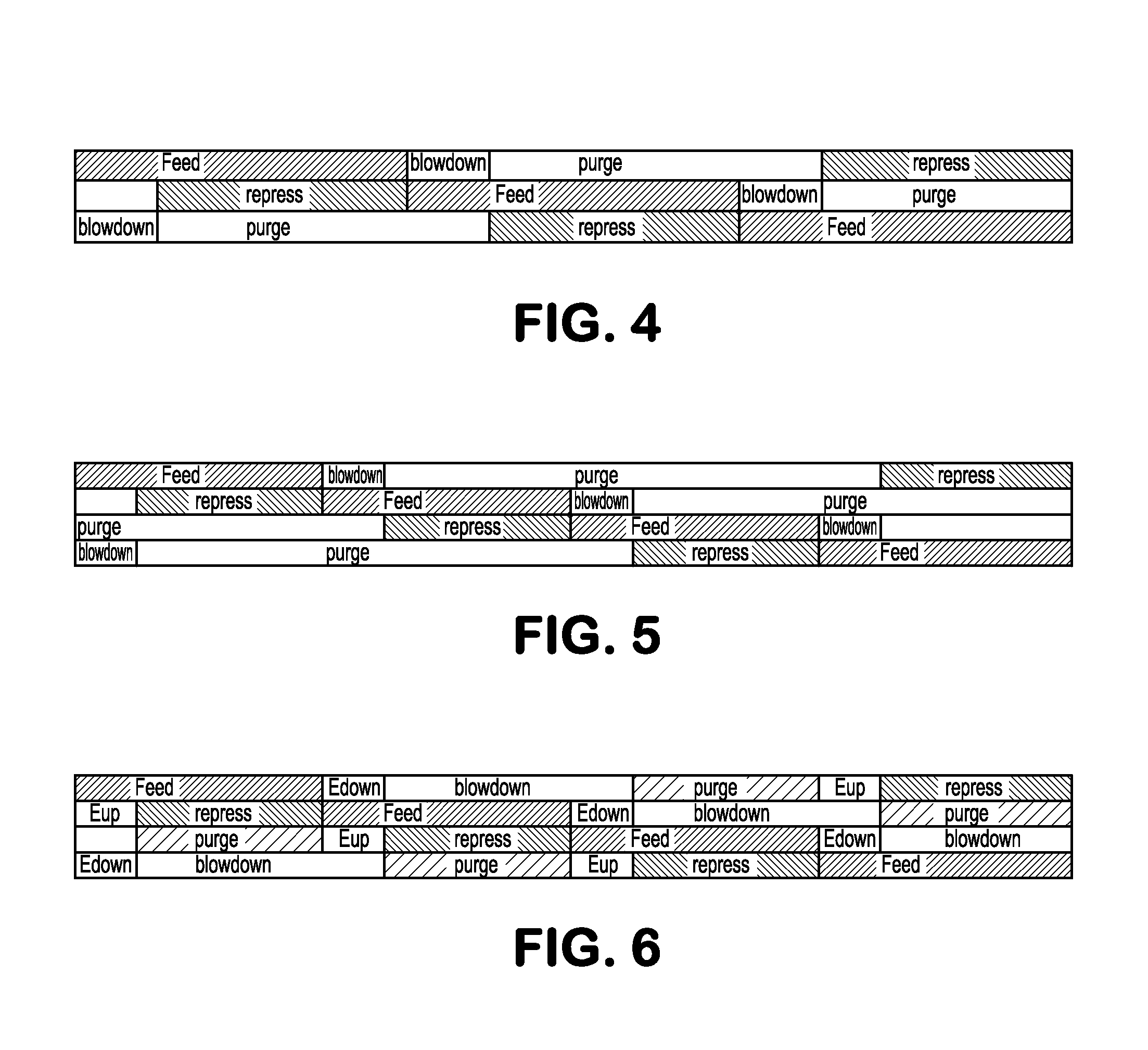
[0099]The following predictive example is based on a configuration for a pressure swing adsorption reactor similar to the configuration shown in FIG. 2. In this example, a mixed-metal oxide based adsorbent is used in a plurality of PSA reactors to separate CO2 and N2. The separation is performed at a temperature between about 400° C. and about 500° C. The PSA reactors correspond to multiple horizontally aligned vessels, such as 3 or 4 vessels. The reactors include an adsorbent configuration suitable for use in a horizontal alignment for input flow perpendicular to the long axis of the reactor, such as parallel plate adsorbents. The reactor vessels have about a 7.5 to 1 length to width ratio, corresponding to a long axis of about 30 meters and a short axis of about 4 meters. The reactors are deployed in a cycle which includes a sequence of steps. The first step in the cycle is a feed step at high pressure, such as ˜...

example 2

Simulations of Separation of a Turbine Exhaust Gas

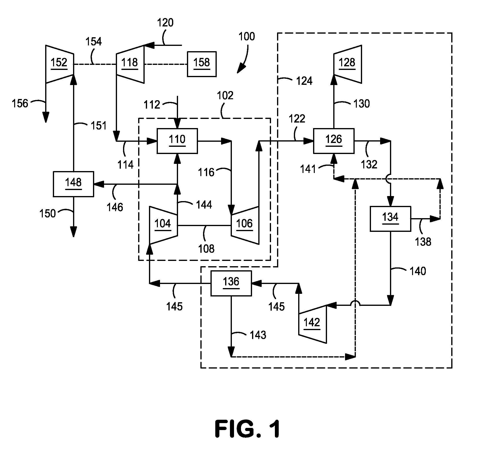
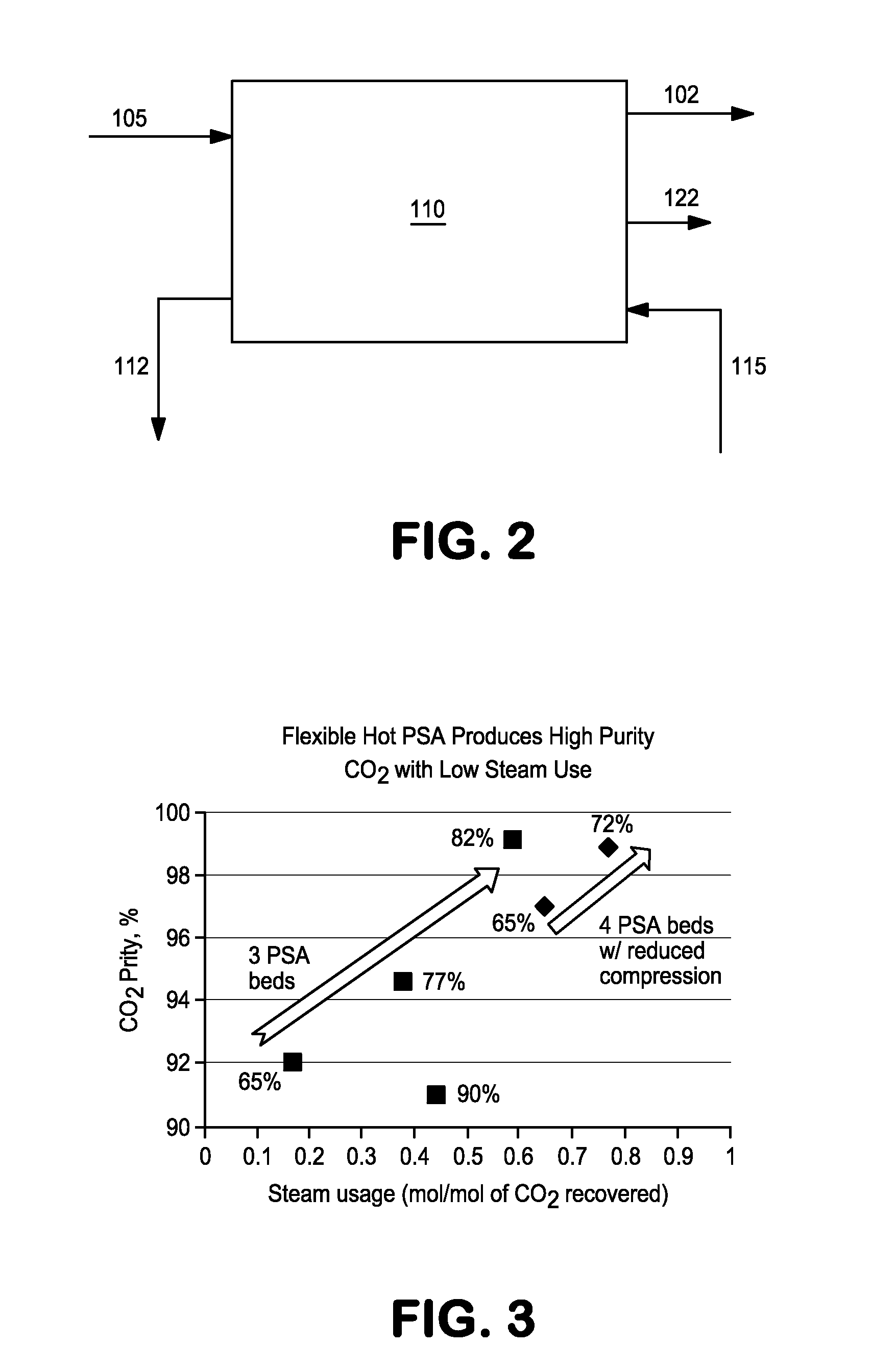
[0100]The following example is based on simulations of separating CO2 from N2 in a flue gas or exhaust gas from a turbine for power generation. The simulations were based on numerical solution of the transient material and energy balances involved in a cyclic adsorption / desorption process. The reactor configuration corresponded to the configuration shown in FIG. 2.

[0101]Table 1 shows the inputs and results from the simulation. The simulated flow of exhaust gas was about 820 million SCF / day. The columns corresponded to various steps in a pressure swing adsorption cycle using a mixed-metal oxide based adsorbent containing potassium carbonate and lanthanum oxide. The “Feed” and “Steam Purge” columns corresponded to inputs into the process, while the remaining columns corresponded to output flows.

TABLE 1SteamBlowFeedPurgeN2 ProductCO2 productDownP (bara)211.520.71.351.35T (° F.)826826837824837MMSCFD82281.365315891.4lb · mol / hr90200893071...

example 3

Energy Requirements for CO2 Separation

[0104]Use of pressure swing adsorption for separating CO2 from an exhaust gas can provide advantages in comparison with conventional separation methods. Table 3 shows a comparison of estimates for total energy consumed while performing CO2 separation using pressure swing adsorption versus two comparative amine separation processes.

TABLE 3EnergySorptionconsumptionPressurePfinal CO2Pfinal N2(kJ / mol CO2,Conditions(kPa)(kPa)(kPa)estimated)Low Pressure Amine10110110118.2(40° C.)High Pressure1919101191923.3Amine (40° C.)Pressure Swing1919101191919.1Adsorption (432° C.)

[0105]In Table 3, the low pressure and high pressure amine processes refer to separation of CO2 by adsorption in an amine separator. The amine separation was performed at a temperature of ˜40° C. The sorption pressure refers to the pressure of the exhaust stream entering the separation process. The Pfinal CO2 value was constant and reflects the low pressure (such as ambient pressure) nat...


PUM

PropertyMeasurementUnit
Temperatureaaaaaaaaaa

Abstract

Systems and methods are provided for combined cycle power generation while reducing or mitigating emissions during power generation. Recycled exhaust gas from a power generation combustion reaction can be separated using a swing adsorption process so as to generate a high purity CO2 stream while reducing/minimizing the energy required for the separation and without having to reduce the temperature of the exhaust gas. This can allow for improved energy recovery while also generating high purity streams of carbon dioxide and nitrogen.

Description

CROSS-REFERENCE TO RELATED APPLICATIONS[0001]This application claims the benefit of U.S. provisional application Nos. 61 / 659,541, filed on Jun. 14, 2012, and 61 / 810,339, filed on Apr. 10, 2013, the entire contents of both of which are hereby incorporated by reference in their entirety.FIELD OF THE INVENTION[0002]In various aspects, the invention is related to low emission power production with separation and / or capture of resulting emissions.BACKGROUND OF THE INVENTION[0003]Capture of gases emitted from power plants is an area of increasing interest. Power plants based on the combustion of petroleum products generate carbon dioxide as a by-product of the reaction. Historically this carbon dioxide has been released into the atmosphere after combustion. However, it is becoming increasingly desirable to identify ways to find alternative uses for the carbon dioxide generated during combustion.[0004]Combined cycle power plants provide an efficient way to generate electricity from the bur...

Claims


Application Information

Patent Timeline
IPC IPC(8): F02C3/34B01D53/047F02C6/04C01B32/50
CPCF02C3/34F02C6/04B01D53/047B01D2253/1124B01D2256/10B01D2257/504B01D2258/0283B01D2259/40056F23J2215/50F05D2260/61Y02E20/14B01D53/0462Y02E20/16Y02C20/40F02C1/00F02C6/18F01K17/04F02C9/16F05D2220/31F05D2220/32
Inventor SUNDARAM, NARASIMHANGUPTA, RAMESHTHOMANN, HANSCARAM, HUGO S.STARCHER, LOREN K.MITTRICKER, FRANKLIN F.WESTON, SIMON C.WEIGEL, SCOTT J.
Owner EXXONMOBIL UPSTREAM RES CO
Why Eureka
Try Eureka