When the system design does not allow incident angle adjustment, the detectable range of
refractive index and sensitivity will be much restricted.
Only when the system is operated under
wavelength mode, a satisfied measuring
dynamic range can be gained without changing the incident angle, except that the sensitivity is not as good as phase mode measurement.
However, there are several disadvantages:a. The incident
light source and the receiving terminal are not fixed, which will limit the size, weight, and complexity of the
light source system and the optical detection system.
This also means that a detection method of a phase mode and an amplitude mode will be restricted.b. The resolution, accuracy, and stability, of a rotation stage are not as good as a linear motorized stage.
Besides, two rotation stages are not cost effective compared to a
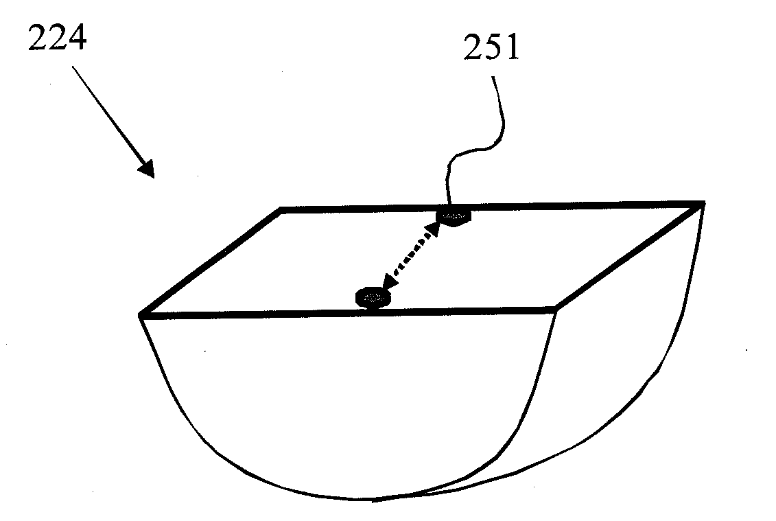
linear stage.c. Due to the structural limitation of optical elements, the
coupling side of the
coupling prism is mainly oriented vertically.
As a result, the
system stability and measurement consistency in the long time use are not easy to maintain.d.
This beam deflection caused by incident angle tuning will result in the impossibility of implementing phase detection.
In the last few years, although the models of all kinds of detection
modes have different advantages, there is still a lack of the design that can integrate several
modes into one device.
With current devices, operation
modes (
resonance angle mode and amplitude measuring mode) with a
large dynamic range usually cannot meet the requirement of high sensitivity, and the incident angle of the light beam in a device performing a phase mode is usually fixed; therefore, its
dynamic range is extremely small.
However, the accuracy and stability are not satisfying.
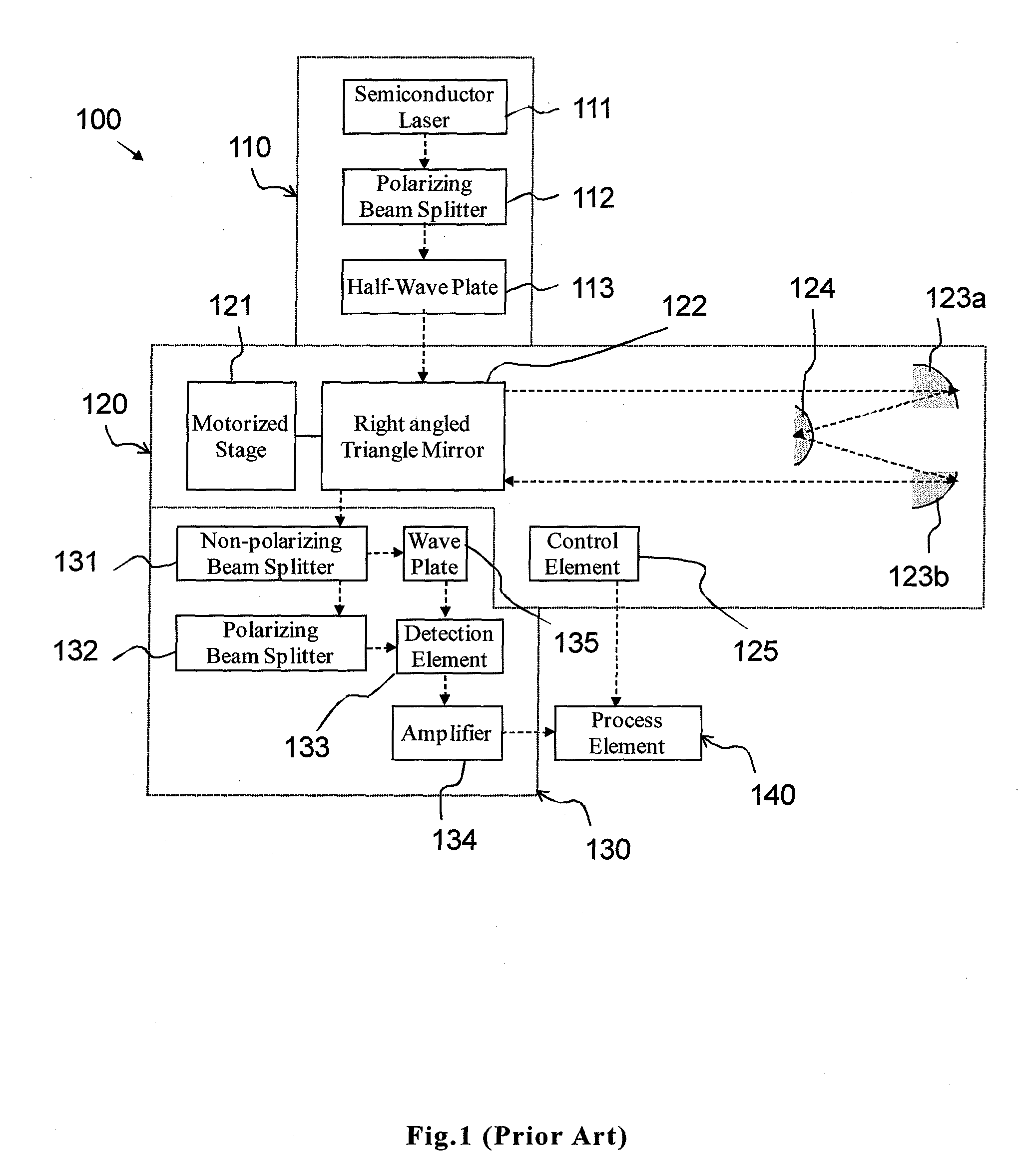
However, hemisphere lens and the two-dimensional mirror will both cause the complexity in light path adjustment and beam path deflection after long time operation.
Slight deflection in the light path of the incident light will cause an error in the incidence angle and the enlargement of deflection in the light path.
This shortage will cause difficulty in the detection of the optical phase and the
resonance angle for the receiving terminal, which might cause a detection error or, in the worst
scenario, a situation of not being able to implement the detection.
Moreover, the system needs to be used with two two-dimensional off-axis parabolic mirror 123a and 123b at the same time; This will cause much more difficulty in the adjustment of positions of the three optical components.
Therefore, users cannot easily scan the full incident angle without changing the light path to the detection unit 130.
When the implementation of the angle scanning with a
large range without the occurrence of light path deflection is desired, it will take a long time to adjust the relative positions of the coupling
prism and two off-axis parabolic mirrors as well as the path incident light.
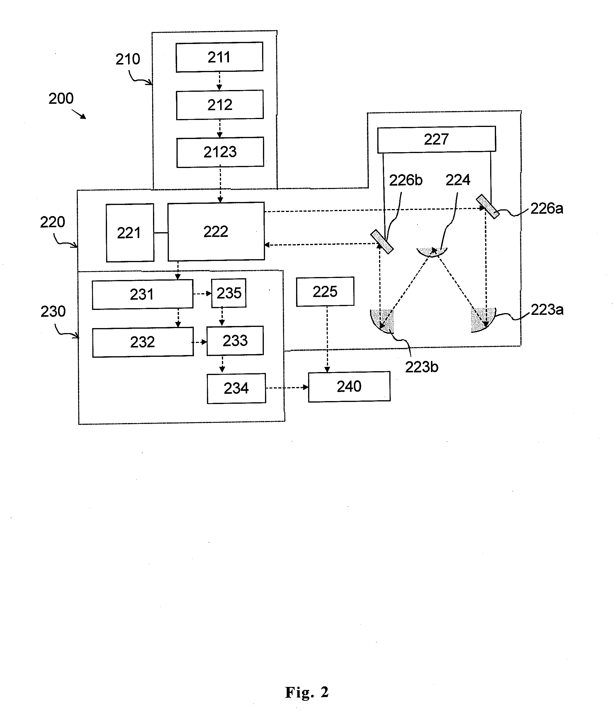
Moreover, this design is not equipped with a mirror that directs horizontal propagation light into vertical propagation, so it's not easy to be integrated into a
microscopy system.

