
Graphene-based steel tubes, pipes or risers, methods for the production thereof and the use thereof for conveying petroleum, gas and biofuels

a graphene-based steel tube and riser technology, applied in the direction of rigid pipes, foundry moulding apparatus, water supply installation, etc., can solve the problems of large-scale production of 2d graphene nanosheets, insufficient utilization of graphene-based diversities, and inability to fully exploit graphene-based diversities

Active Publication Date: 2014-05-29
UNIVE ESTADUAL DE PONTA GROSSA
View PDF7 Cites 28 Cited by
  • Summary
  • Abstract
  • Description
  • Claims
  • Application Information

AI Technical Summary

Benefits of technology

The present invention is about using graphene to improve the strength and integrity of steel tubes, pipes, or risers used for transporting oil, gas, and biofuels. The invention is based on a method of manufacturing steel tubes using a specific process that involves incorporating graphene into the steel to create a new material with superior properties. The technical effects of this invention include improved structural integrity, higher yield strength, and better resistance to corrosion and fatigue. The invention also addresses the limitations of current methods for producing graphene and provides a solution for large-scale production of graphene-based steel tubes.

Problems solved by technology

However, the diverse potential of graphene have not yet been fully exploited, since the first graphene sheets have been synthesized experimentally in 2004 only obtained through the reduction of graphite.
The procedures for obtaining graphene still have some limitations due to the low yield of final product.
The large-scale production of 2D graphene nanosheets remains a major challenge.
It should be noted that some steel products for use in pipelines, including higher levels of resistance, still lack a practical use, although its development is in early stages.
Concerning its structure, the risers can be flexible or rigid, or even a combination of both types, and constitute a part of the overall cost in the fields of oil exploration.
These costs are related to the stages of manufacture, installation and maintenance of such structures.
The steel catenary risers exceed the use which may not be possible to use flexible risers (e.g. in terms of temperature, pressure or diameter in adverse conditions).
However, since the recent discovery of a gigantic source of oil in the pre-salt layer of Brazil, specifically in the area of the Santos Basin in ultra deep water (5000-7000 m), there is a technical limitation to the use of flexible risers.
This limitation has stimulated the design modification of existing pipelines.
This crack growth is often accompanied by large increase in the plasticity of the material in relation to a stationary crack.
High pressure tubes, however, have low plastic constraint because they are thin-walled structures, which do not favor the establishment of plane strain state.
In addition, there is the formation of a condition of low triaxial loads resulting from the predominance of the membrane tension (due to the internal pressure).
Note, however, that the crack propagation in steel pipe is not only due from the (internal or external) pressure in a deep-sea submarine environment, but also a consequence of fatigue and structural defects of the metallic component.
In microalloyed steels, the rolling technique produces considerable effects on the microstructure of the steel, such as the formation of cavity during the fracture process.
When the conformation of the tube is made by rolling process by “cold work”, the deformation is associated with increased inner tension, or stored energy, material and tends to decrease the ductility.

Method used


Image

  • Graphene-based steel tubes, pipes or risers, methods for the production thereof and the use thereof for conveying petroleum, gas and biofuels
  • Graphene-based steel tubes, pipes or risers, methods for the production thereof and the use thereof for conveying petroleum, gas and biofuels
  • Graphene-based steel tubes, pipes or risers, methods for the production thereof and the use thereof for conveying petroleum, gas and biofuels

Examples


example 1

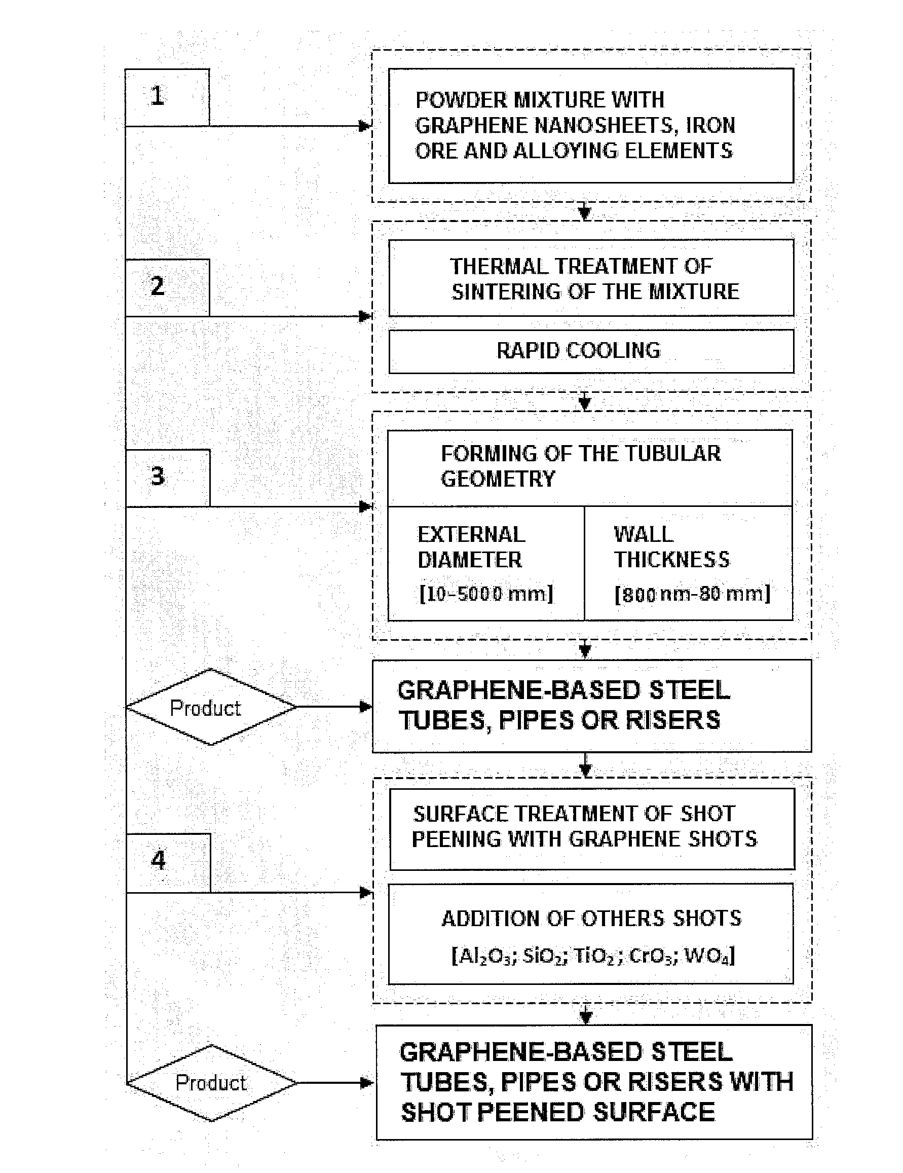
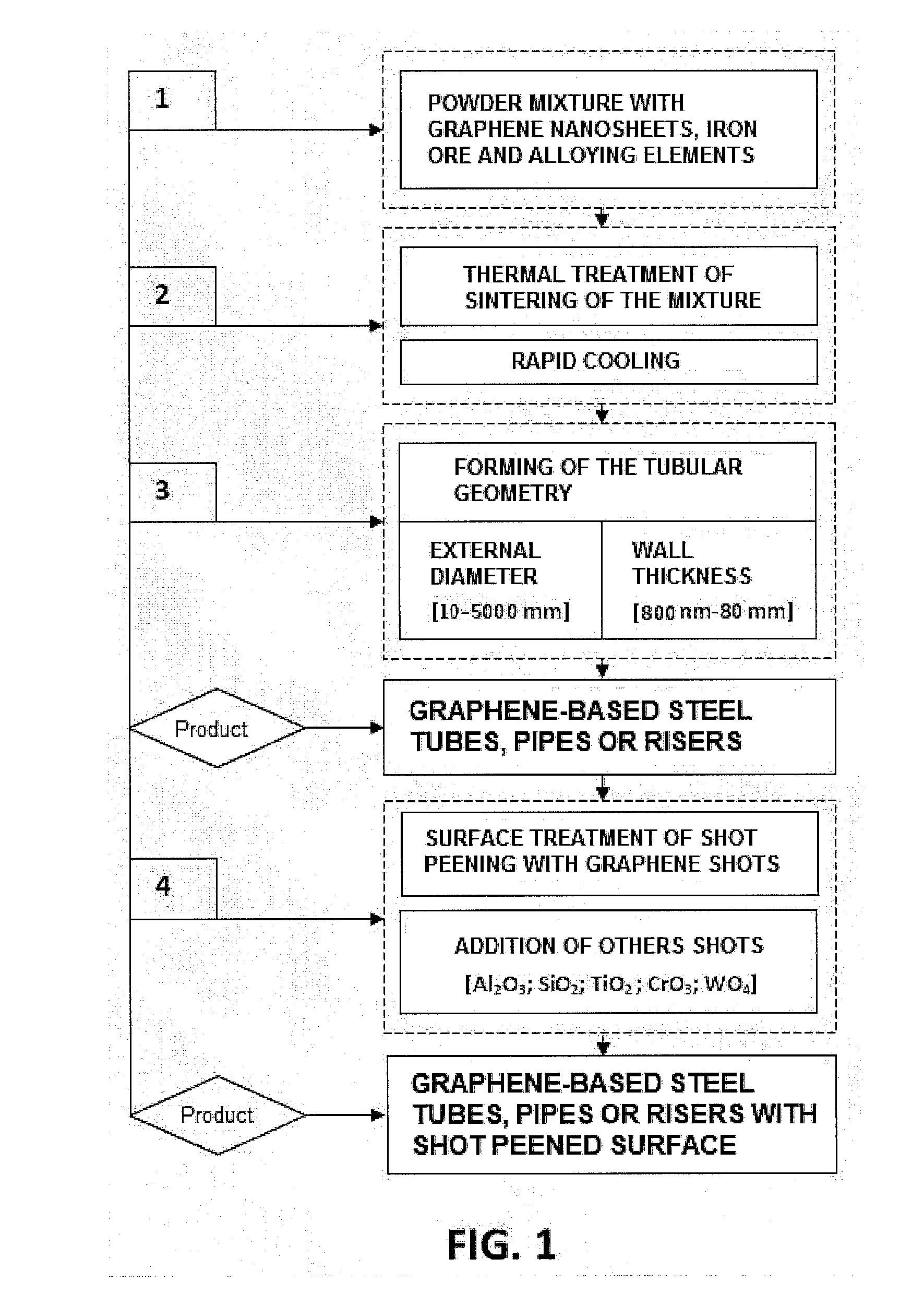
[0231]Method of manufacturing a graphene-based steel riser with chrome surface, which comprises the following steps:[0232]i) to make the precursor mixture of graphene sheets by 0.2% (C, wt %) with surface area of 2300 m2 / g, and average size (lateral) of 30 μm, and add (wt %) 0.08% Si; 0.02% Al; 0.2% N, 0.03% Nb; 2.0% Mn; 0.8% Ni; 0.01% Ti; 0.07% V; 0.1% Mo; 0.8% Cr; 0.001% Cu; and Fe balanced;[0233]ii) heat treating the graphene-based steel mixture in arc furnace at a temperature of 1200-3000 K, said heat treatment that produces at least the austenite;[0234]iii) to effect the conformation of the tubular geometry by hot rolling with a diameter of 2000 mm (outer wall), and wall thickness of 3.0 mm;[0235]iv) to make the blasting of the tube surface with granules of graphene (average size of 30 μm) and CrO3 (average size of 50 μm) combined in the ratio (1:1), whose jets are released under pressure of 1.0 MPa for 200 s at a distance of 70 mm between the jet nozzle and the pipe;[0236]v) t...

example 2

[0237]Method of manufacturing a luminescent graphene-based steel pipeline, which comprises the following steps:[0238]i) to make the precursor mixture of graphene sheets 0.90% (C, wt %) with surface area of 1200 m2 / g and average size (lateral) of 15 μm, and add (wt %): 0.03% Si; 0.02% Al; 0.2% N, 0.03% Nb; 2.0% Mn; 0.8% Ni; 0.01% Ti; 0.06% V; 0.1% Mo; 0.8% Cr; 0.001% Cu; and Fe balanced;[0239]ii) heat treating the graphene-based steel mixture in arc furnace at a temperature of 1500-1773 K;[0240]iii) to effect the conformation of the circular tube geometry by hot rolling with a diameter of 150 mm (outer wall), with wall thickness of 1.27 mm;[0241]iv) to make the blasting of the tube surface with granules of graphene (average size of 50 μm), whose jets are released under pressure of 1.0 MPa for 150 s at a distance of 60 mm between the jet nozzle and the pipe;[0242]v) to make the coating of the blasted surface with SrAl2O4:Ce, Dy coating layer by chemical vapor deposition (CVD), at a di...

example 3

[0243]Method of manufacturing an ultrathin graphene-based steel tube with antibacterial surface blasted with TiO2, which comprises the following steps:[0244]i) to make the precursor mixture of graphene sheets 0.03% (C, wt %) with surface area of 2000 m2 / g and average size (lateral) of 10 μm, and add (wt %): 0.17% Si; 0.021% Al; 0.63% N, 0.052% Nb; 0.56% Mn; 0.20% Ni; 0.013% Ti; 0.03% V; 0.13% Mo; 0.12% Cr; 0.002% Cu; and Fe balanced;[0245]ii) heat treating the graphene-based steel mixture in plasma arc furnace at a temperature of 1200-2500 K, said heat treatment that produces at least the austenite;[0246]iii) to effect the conformation of tubular square profile geometry 300×300 mm (outer wall) and wall thickness of 500 μm by hot rolling and folding;[0247]iv) to make the blasting of the tube surface with granules of graphene (average lateral size of 20 μm) and TiO2 shots (average size of 30 μm), combined in the ratio (1:1), whose jets are released under pressure of 0.5 MPa for 200 s,...


PUM

PropertyMeasurementUnit
grain sizeaaaaaaaaaa
outer diameteraaaaaaaaaa

Abstract

The present invention relates to new graphene-based steel tubes, pipes or risers, whose products are obtained by a method of manufacturing that consists in adding graphene nanosheets, heat treatment, forming tubular geometry and surface finish. In addition to the unique chemical composition based on graphene, with carbon content ranging between 0.01 and 21.0%, these products have the wall thickness between 800 nm and 80 mm (from ultra fine to thick), diameter between 10 and 5000 mm, and having a tensile strength not less than 2000 MPa reaching up to 50 GPa, with far superior features to those obtained by other methods. Such products can be used for petroleum, natural gas and biofuels transportation, including in deepwater submarine riser systems (>1500 m), with direct application in the oil industry.

Description

CROSS-REFERENCE TO RELATED APPLICATIONS[0001]This application is a National Stage of International Application No. PCT / BR2011 / 000415, filed Nov. 4, 2011, which in turn claims the benefit of Brazilian Patent Application PI1102980-3, filed Jun. 7, 2011. The entire disclosures of the above applications are hereby incorporated herein by reference.TECHNICAL FIELD[0002]The present invention relates to new graphene-based steel tubes, pipes or risers, whose specificities of geometry, chemical composition, microstructure and mechanical properties allow its use for transporting oil, gas and biofuels. This technical solution aimed at improving the structural integrity of such tubes, pipes, or risers produced according to an exclusive method of manufacturing, and that have qualities much higher than those without graphene. The products of this invention have an impact on the transportation of energy, production and use of equipments in the oil field, in deep water subsea riser systems (>1500...

Claims


Application Information

Patent Timeline
Patent Type & Authority Applications(United States)
IPC IPC(8): F16L9/02B22D25/02B22F5/10
CPCF16L9/02B22F5/106B22D25/02B82Y30/00C22C38/001C22C38/02C22C38/04C22C38/06C22C38/42C22C38/44C22C38/46C22C38/50C22C38/52C22C38/56C22C26/00C22C33/0228C22C2026/001B22F2003/242B22F2998/10C22C2026/002C01B32/16C01B32/194Y10T137/0318C01B32/21C01B32/156C22C1/1084C22C1/1036B22F3/105B22F3/1028B22F3/17B22F3/18B22F3/20B22F2003/166C23C14/00C23C16/00
Inventor MOREIRA DE CARVALHO, ANDRE LUISZURBA, NADIA KHALED
Owner UNIVE ESTADUAL DE PONTA GROSSA
Features
  • Generate Ideas
  • Intellectual Property
  • Life Sciences
  • Materials
  • Tech Scout
  • Unparalleled Data Quality
  • Higher Quality Content
  • 60% Fewer Hallucinations
Learn More