
Staged biomass fractionator

Inactive Publication Date: 2014-07-03
COOL PLANET ENERGY SYST
View PDF6 Cites 20 Cited by
  • Summary
  • Abstract
  • Description
  • Claims
  • Application Information

AI Technical Summary

Benefits of technology

The patent describes a method and system for heating and decomposing carbon-containing material, such as biomass, to produce vapor and solid streams with beneficial characteristics. The system includes a screw design that improves mixing and rigidity in a hot environment. The method also includes using filters, temperature quench, and cyclones to remove heavy coke-forming or particulate components that decrease catalyst coking rates. The pressure within the reactor can be selectively controlled by restricting the rate at which products are withdrawn. The transfer screw has flights and a shaft designed to promote mixing of biomass and vapor flow. The flights have a repeated portion to promote vapor flow and solids mixing. Overall, the patent provides a technical solution for efficiently producing valuable chemicals and fuels from carbon-containing materials.

Problems solved by technology

Rising energy costs, concerns about the continued use and availability of non-renewable sources, and concerns about the effects of the use of fossil resources on global climate change have become some of the major technological challenges facing humanity.
At the low extreme, simple everyday cooking typically drives off water and starts to de-hydrolyze the biomass, causing the darkening and carmelization that we all associate with cooked foods.
Although some pyrolyzers are focused simply on producing syngas, there is considerable effort in the development of milder pyrolyzing conditions, which typically results in a condensed liquid commonly called bio-oil.
The fundamental problem with the resultant pyrolysis oil from a biomass feedstock is that it is made up of hundreds to thousands of compounds, which are the result of subjecting the raw biomass to a wide range of temperature, time, and pressure profiles in bulk.
When this process is complicated by the thousands of major bio-compounds in the original bio-feedstock, the result is a nearly intractable array of resultant compounds all mixed together.
Pyrolysis oils from such processes are typically not thermodynamically stable.
Also, attempts to re-vaporize pyrolysis oil typically result in additional chemical reactions, which produce additional biochar and a shift to lower molecular weight components in the resulting gas stream.
Although fairly high yields of pyrolysis oil can be achieved in laboratory scale experiments, larger industrial scale demonstration projects typically produce much lower yield.
Unfortunately, catalytic conversion of bio vapors is associated with higher coking rates and catalytic deactivation.

Method used


Image

  • Staged biomass fractionator
  • Staged biomass fractionator
  • Staged biomass fractionator

Examples


example 1

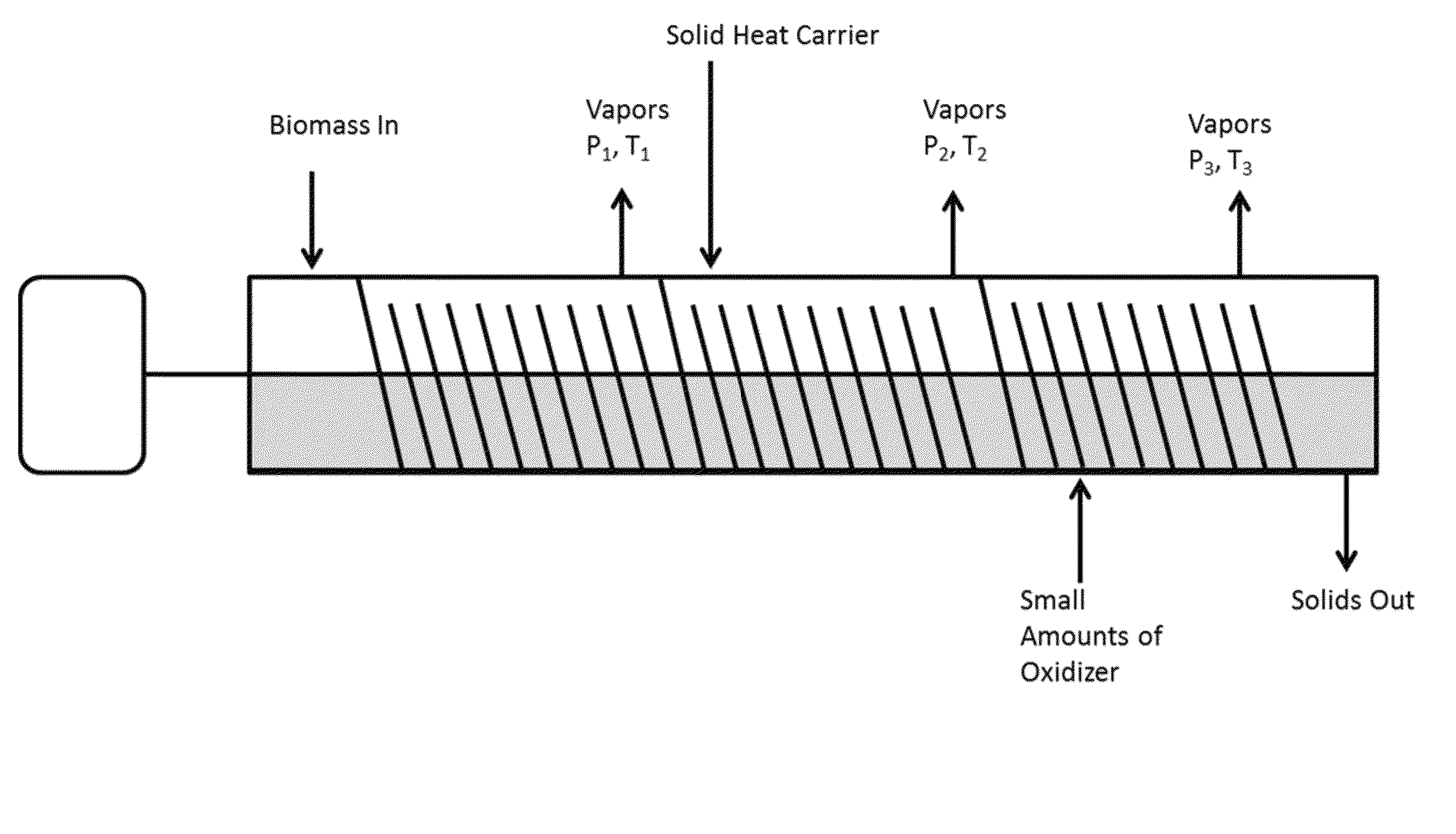
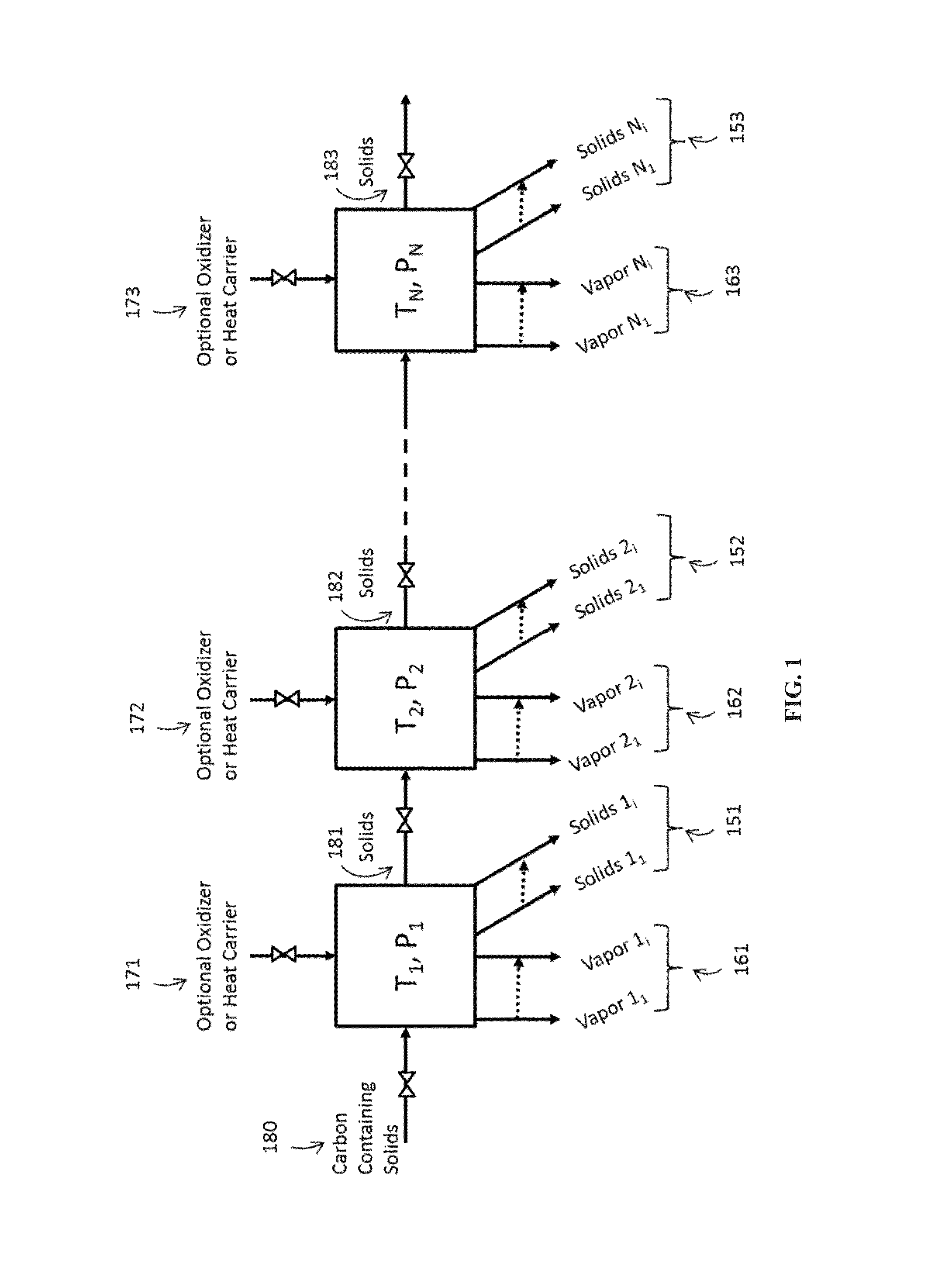
[0132]In a series of experimental tests the staged pyrolysis benefits were tested by varying the generation temperature of the second stage vapors. Example 1 models a two stage process, in which the first stage is conducted under varying conditions to make vapors for fuel. These vapors were then directed to a catalytic process to produce fuel and several key indicators were observed. The second stage could be conducted under conditions to convert the solid stream into a biochar for soil amendment. The reaction conditions for the first stage were varied and the effect of the reaction conditions on catalyst lifetime and coke production were evaluated.

[0133]Coke yield and relative catalyst life is reported in Table 1. The table is normalized to generic mass units per hour and temperature is controlled by varying the electric heaters used in the experiment. The measured catalyst life is also normalized against “x” amount of time that fuel is produced without significant reactant breakth...

example 2

[0135]This examples illustrates a three step system where the first step produces vapors not suitable for fuel product and the second step vapors are used to make fuel. The third step is to make biochar for soil amendment. This example also shows the different use of heating methods and how pressure can be higher in the second stage (compressor).

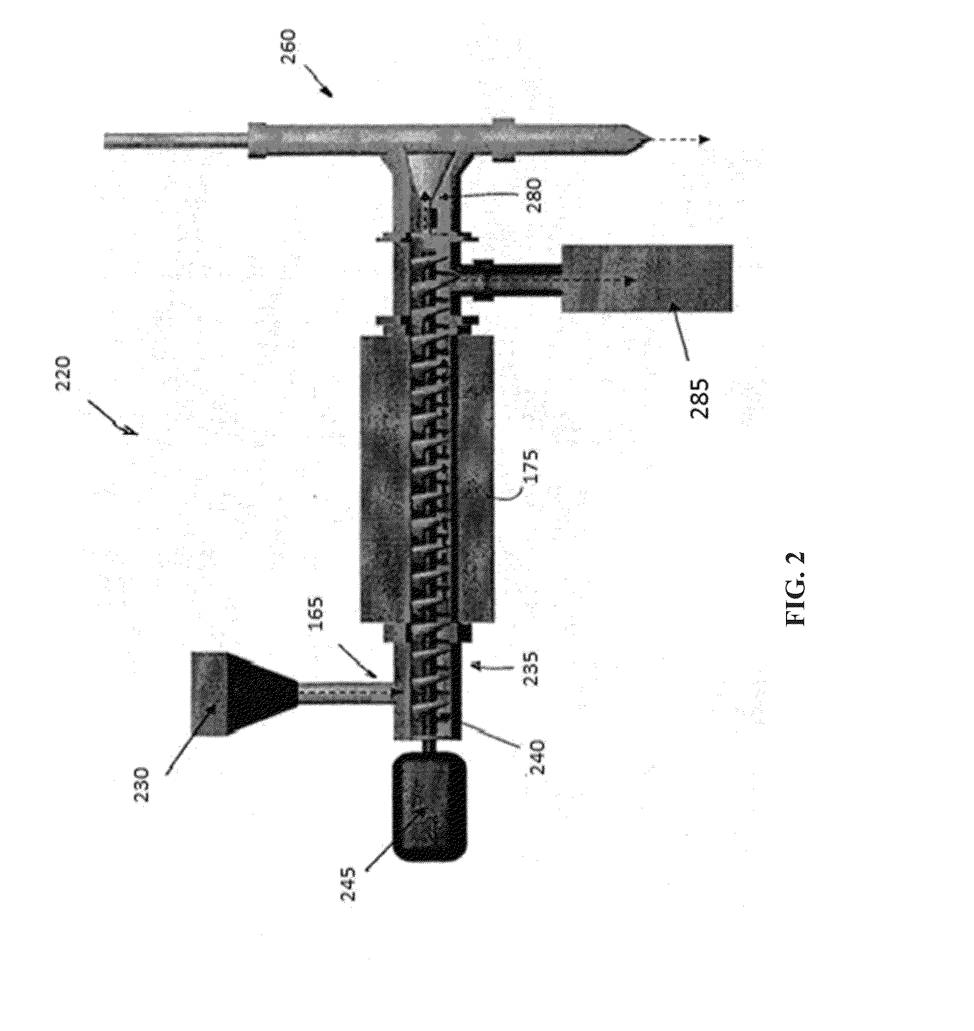
[0136]Referring to FIG. 3, biomass, pine chips, is fed into the feeding system at point 165 and introduced into the first auger. The auger is heated externally such that the internal temperature is 160° C. (320° F.) and the pressure is at atmospheric. The vapor product is primarily water and is withdrawn from port 361 on 321 and sent to a water treatment stage.

[0137]In this example the solids are also introduced into a second auger via a feeding system 166. Heated steel shot are fed through the feeding system at point 176 on 322 and introduced into the second auger. The second auger 322 operates at a pressure of 60 psig by the introduction o...

example 3

[0140]This example shows a three step system in which the heating of the middle stage is accomplished using electricity through the shaft.

[0141]Referring again to FIG. 3, biomass such as pine chips are fed into the feeding system at point 165 and introduced into the first auger. The auger is heated externally such that the internal temperature is 250° C. (480° F.) and the pressure is at atmospheric. The vapor product is primarily water and acetic acid and is withdrawn from port 361 on 321 and sent to another process. There are several processes that might use the acetic acid, such as a neutralization process in a water treatment step. As noted previously, removal of acetic acid at this stage helps reduce coking during fuel production. This ensures that the vapor stream generated at the lower temperatures are not sent to the catalytic process where said acetic acid is known reduce operation time of the catalyst but rather said vapors may be used for a separate beneficial process.

[014...


PUM


Abstract

Various biomass reactors systems and methods of pyrolyzing biomass are disclosed. One type of biomass reactor system comprises a plurality of biomass processing stations configured in series, each station comprising an auger reactor including an auger inlet for receiving biomass and a transfer screw for conveying the biomass through the auger reactor.

Description

RELATED APPLICATIONS[0001]This application claims the benefit of priority under 35 U.S.C. §119(c) to U.S. Ser. No. 61 / 799,446, filed Mar. 15, 2013, entitled “Staged Auger System”, U.S. Ser. No. 61 / 881,309, filed Sep. 23, 2013, entitled “Thermal Biomass Processor” and U.S. Ser. No. 61 / 891,872, filed Oct. 16, 2013, entitled “System and Method for Synthesizing Renewable Chemicals Utilizing Simultaneous Parallel Fractionation,” the contents of which are incorporated by reference.[0002]This application also is a continuation-in-part application of U.S. Ser. No. 13 / 797,985, filed Mar. 12, 2013, entitled “Biomass Reactor,” which is a continuation in part of U.S. Ser. No. 13 / 398,596, filed Feb. 16, 2012, entitled “Biomass Reactor”, which is a divisional of U.S. Ser. No. 12 / 688,523, filed Jan. 15, 2010, entitled “System and Method for Biomass Fractioning” which claims priority from Provisional Application No. 61 / 146,079, filed Jan. 21, 2009, entitled “System and Method for Biomass Fractionin...

Claims


Application Information

Patent Timeline
IPC IPC(8): C10B7/10
CPCC10B7/10C10B47/02C10B47/44C10B53/02C10B57/02C10C5/00F26B3/18F26B25/002F26B2200/02F23G5/027F23G5/16F23G5/50F23G7/10F23G2201/304F23G2202/60F23G2203/8013F23G2204/20F23G2900/50001C10B49/16Y02E50/10Y02E50/30C10L5/44
Inventor DAUGAARD, DARENTONG, DAVYTRAXLER, VERN S.AELION, VITALPODREBARAC, GARYHILLIER, JAMESCHEIKY, MICHAEL C.
Owner COOL PLANET ENERGY SYST
Learn More