Terahertz modulator

a modulator and terahertz technology, applied in the field of terahertz, can solve the problems of ineffective photon working, high working frequency, and inability to effectively work with photons, and achieve the effects of improving modulator efficiency, reducing the confinement of electromagnetic fields, and reducing the cost of operation

Inactive Publication Date: 2014-07-10
CENT NAT DE LA RECHERCHE SCI
View PDF15 Cites 17 Cited by
  • Summary
  • Abstract
  • Description
  • Claims
  • Application Information

AI Technical Summary

Benefits of technology

[0009]The resonance effect of the dielectric function of a polar crystal in the so-called Reststrahlen frequency band of the crystal is thus used to create a terahertz modulator of remarkable efficiency which operates at ambient temperature. The modulator can operate in reflection, the variation of the intensity of the coupling between the interface phonon polariton and the incident radiation resulting in a variation of reflectivity of the component at the wavelength of the incident wave, or in transmission, according to the implementation of the component.
[0010]Advantageously, the polar crystal has two interfaces with a dielectric medium, said interfaces being sufficiently close to allow the coupling of interface phonon polaritons propagating along each of the interfaces. The coupling of two interface phonon polariton modes allows the confinement of the electromagnetic field to be further accentuated and the efficiency of the modulator to be improved, notably by making the variation of the coupling more sensitive by the means of control.

Problems solved by technology

The devices in the terahertz domain come up against intrinsic operating limits: the working frequencies are too high for components based on electronics and the energies are too low to work effectively with photons.
Nevertheless, as the results published in this document show, such control is limited, including at low temperature.

Method used


Image

  • Terahertz modulator
  • Terahertz modulator
  • Terahertz modulator

Examples


first embodiment

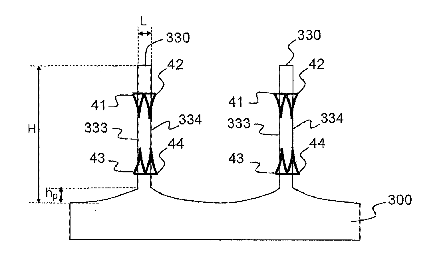
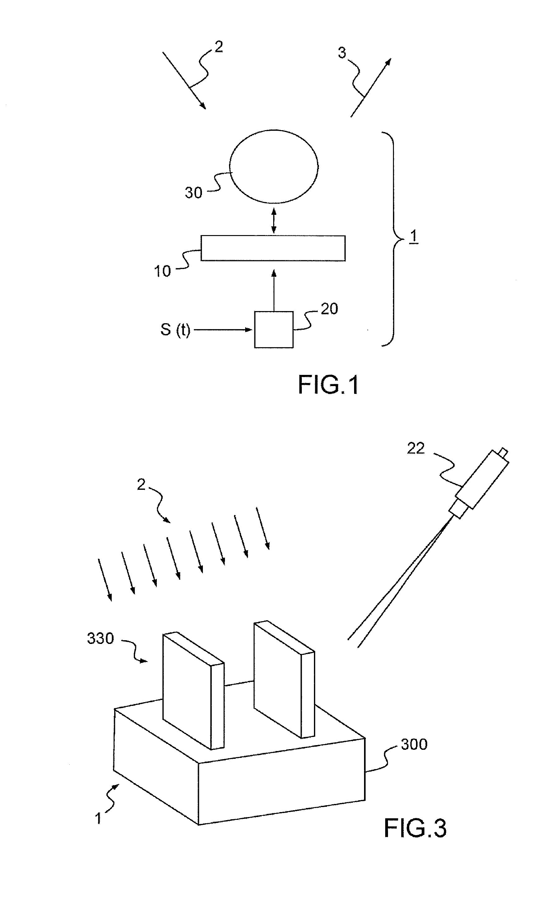
[0054]FIGS. 3 and 4A show a first example of a THz modulator according to the In this example, the polar crystal is structured to form at least one crystal blade 330, each blade forming an optical antenna allowing coupling with the incident radiation. An optical antenna is generally understood to be an element capable of transferring the energy of an incident radiation to a more confined volume. Optical nano-antennas have been widely studied and the article by L. Novotny et al. (>, Nature Photonics, Vol 5, February 2011) provides a very good description of them. Here, the blade of polar crystal is sized so as to form a resonator the dimensions of which are adjusted as a function of the desired frequency properties of the coupling. The resonator creates an evanescent field that will allow coupling with the incident radiation allowing the energy of the incident wave to be confined.

[0055]In the example described in FIGS. 3 and 4A, each crystal blade 330 presents the shape of a wall th...

second embodiment

[0079]A modulator such as described in FIG. 8 is fabricated for example according to the following fabrication steps. The layers 835, 812, 810, 811 and 837 are deposited by epitaxy on a substrate of doped GaAs 836. UV lithography is then performed in a photosensitive resin to define the geometry of the optical antennas. The layer 837 is chemically etched and the layers composing the optical antennas (attaching layer 838 and metallic layer 834) are deposited by evaporation.

[0080]The electrical means of control 24 can consist of a voltage source connected to the optical antenna grating 834 (electrically connected to each other) and to the mirror 836. The electrical means of control 24 allow the electron density in the quantum well to be controlled. The application of a negative voltage has the effect of raising the conduction band with respect to the Fermi level of the quantum well, leading to a sharp drop in the density of carriers. The inverse effect is obtained by applying a posit...


PUM


Abstract

According to one aspect, the present invention concerns a terahertz modulator (1) intended to be used in a given frequency band of use. The modulator comprises a semi-conductor polar crystal (330) presenting a Reststrahlen band overlapping said frequency band of use and presenting at least one interface with a dielectric medium, coupling means (330) allowing the resanant coupling of an interface phonon polariton (IPhP) supported by said interface and of an incident radiation (2) of pre-determined frequency lying in said frequency band of use and means of control (22) apt to modify the intensity of the coupling between said interface phonon polariton and said incident radiation (2) by modification of the dielectric function of the polar crystal in the Reststrahlen band of the polar crystal (10).

Description

TECHNICAL DOMAIN OF THE INVENTION[0001]The present invention relates to active components in the domain of terahertz frequencies. More precisely, the invention relates to a modulator for terahertz radiations.STATE OF THE ART[0002]The terahertz domain is generally defined by radiations having frequencies of between 0.1 and 30 THz. This frequency band overlaps the domain of electronics and the domain of photonics. The devices in the terahertz domain come up against intrinsic operating limits: the working frequencies are too high for components based on electronics and the energies are too low to work effectively with photons. Nevertheless, this frequency domain has a high potential for applications, for example in the domain of telecommunications in which the frequency ranges usually allocated to telecommunications are becoming saturated. Notably, in the United States, the allocation of ranges of frequencies up to 0.3 THz is already saturated. This potential for applications is encour...

Claims


Application Information

Patent Timeline
Patent Type & Authority Applications(United States)
IPC IPC(8): H01L33/58H01L33/06
CPCH01L33/58G02F1/00G02F1/01G02F2203/13H01L33/06G02F1/0126
Inventor VASSANT, SIMONPARDO, FABRICEPELOUARD, JEAN-LUCGREFFET, JEAN-JACQUESARCHAMBAULT, ALEXANDREMARQUIER, FRANCOIS
Owner CENT NAT DE LA RECHERCHE SCI
Why Eureka
Try Eureka