Passive Micro-vessel and Sensor

a passive micro-vessel and sensor technology, applied in the field of electric passive devices, can solve the problems of severe constraints, hindering operation, and complicating the difficulty of acquiring and performing fluidic samples in such an environmen

Active Publication Date: 2014-07-31
FLUIDION
View PDF1 Cites 70 Cited by
  • Summary
  • Abstract
  • Description
  • Claims
  • Application Information

AI Technical Summary

Benefits of technology

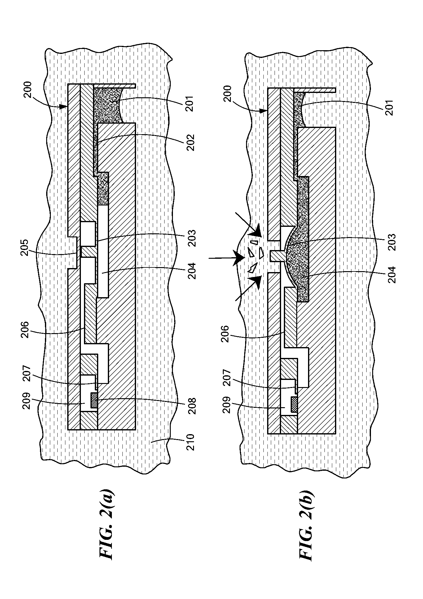
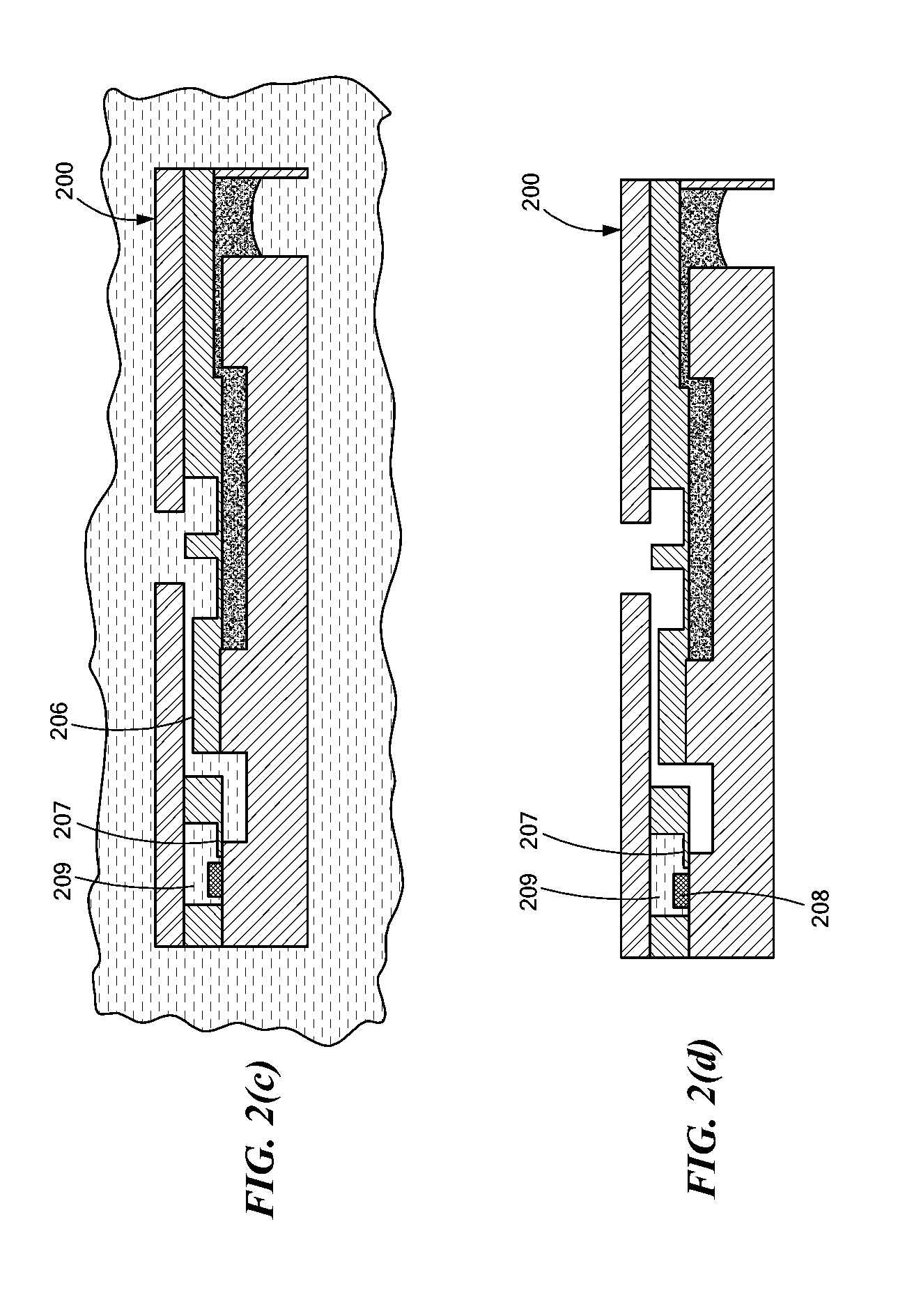
[0038]In accordance with another related embodiment of this invention, a sampling device may be provided that may be remotely triggered. The sampling device may include a passive timing mechanism with a short time constant that allows, such that upon receipt of the trigger signal, a sample can be acquired within a relatively short time interval. Such a passive timing mechanism may combine appropriately-sized timing cavity and timing channel, a timing fluid of appropriate viscosity and a timing fluid pressure of appropriate magnitude, to result in a short timing interval prior to breaking the associated mechanical structure. Such a time interval may be less than 100 ms. In various applications, the time interval may range from 0.1 ms to 10 ms or 10 ms to 1 s. In other time applications the required timing may be significantly longer.
[0039]In accordance with still further related embodiments of the invention, a monitoring system is provided for monitoring the sampling acquisition process, and, without limitation, to record a time-stamp, allowing precise recording of sample acquisition time by the sampling device.

Problems solved by technology

Such operations are hindered by the harsh subterranean environment specific to oilfields, including high temperature and pressure (HPHT), corrosive fluids, and severely constrained geometry.
The difficulty in acquiring and performing measurements on fluidic samples in such an environment are further complicated by use of electronic sensors that typically require power, monitoring and / or telemetry.
Measurements of fluid properties and composition from an oil well are difficult to perform in the oilfield environment.
Measurements need to be performed in other types of situations, where the deployment of active sensing systems with on-board electronics and data transmission capabilities may either be impossible due to environmental issues (for example temperatures and pressures that are too high) or may prove to be too expensive to justify economically.
In most cases, these instruments are operated using electrical power, and require sample manipulations that are difficult to automate.
In some environments such instruments may be impractical due to their size (such as in difficult to reach areas, or within downhole oilfield tools), may be dangerous due to their electrical operation (inside explosive environments such as refinery facilities and tanks, near oil and gas wells), may be incompatible with the shocks or vibrations (within an oil well), or may be simply difficult to adapt.
Additionally, samples are often required in environments that pose objective risks and dangers, or that are physically remote, or where frequent sampling using manual devices may prove impractical: sites of nuclear disasters, military battlegrounds, biohazard or chemical hazard areas, terrorist attack sites, remote natural resources such as rivers and lakes, coastal waters and other offshore locations, deep water and sub-sea environments.
In such cases, robotic equipment may need to be deployed, and the capability to take and analyze such samples may provide important information that cannot be acquired using the on-board in-line sensors present on such equipment.
Certain chemical or biochemical sample preparation protocols may require more complex sample manipulations, such as reaction with a first reagent, waiting for an incubation or reaction time, and then bringing the sample in contact with a second reagent.
In certain applications, the moment when a sample needs to be acquired may not be known in advance, so that a pre-programmed sampling sequence may not be appropriate.
Unintended leaks, spills or discharges occur frequently around industrial sites, and may affect environments such as the deep ocean (off-shore environment), a river, a lake, an estuary, the coastal water, or the atmosphere.
However, technology today is very limited in terms of deployment and ability to acquire a significant number of samples at multiple depth points, at multiple radial points from the source and at multiple points in time.
Additionally, in most cases, the sampling capability is also not located at the industrial site, but more likely on-shore and may take days for the equipment to reach the offshore facility.
Similarly, in a deep-water environment near hydrocarbon production facilities, there is a risk of methane hydrate formation.
This provides a serious risk of blockage, contamination and / or unrepresentative sampling.
This movement may, or may not, be in the same direction at all times, may not be predictable, and may cause the sampling unit or string of units to be in a position that is not vertically above the original anchoring point, or vertically below a buoy or similar water-surface mooring point.
Consequently, this may cause error in the assumed position data associated with the sampling unit or array.
Currently, sample loading and measurement protocols for microbiological measurements often need to be performed manually, requiring specialized labor and equipment and incurring significant costs.
This protocol provides a risk of human error in the sampling and / or transportation procedure, leading to an unrepresentative sample being collected, or to sample contamination and / or degradation during transport.
These moments may depend of certain external events that cannot be predicted or anticipated at sampler installation, and therefore the sample acquisition moments cannot be pre-programmed in the sampler design.
It is important that any timing mechanism used to trigger the acquisition of a fluid sample be accurate, however in certain applications such timing may not prove accurate enough.
For example, timing errors in fluidic clocks may occur due to small manufacturing imperfections that may change the overall timing of the sample acquisition.
For example, a ten percent relative error in the volume of a timing cavity will result in a ten percent relative error in the timing of that particular sample acquisition.
If the overall timing was designed to be ten hours, a ten percent error will introduce a one-hour absolute error in the timing, so the sample may be acquired an hour prior to, or an hour later than the scheduled time.
Such timing errors provided by fluidic clocks may become particularly problematic when a series of samples needs to be acquired in sequence.
If there is a ten percent error in the fluidic clock of each sampling device, that means that it is likely that the order of the sampling events will be disturbed.

Method used


Image

  • Passive Micro-vessel and Sensor
  • Passive Micro-vessel and Sensor
  • Passive Micro-vessel and Sensor

Examples


Embodiment Construction

[0163]In illustrative embodiments, an electrically passive device and method for in-situ acoustic emission, and / or releasing, sampling and / or measuring of a fluid or various material(s) is provided. The device may provide a robust timing mechanism to release, sample and / or perform measurements on a predefined schedule, and, in various embodiments, emits an acoustic signal sequence(s) that may be used for triangulation of the device position within, for example, a hydrocarbon reservoir or a living body. Details are discussed below.

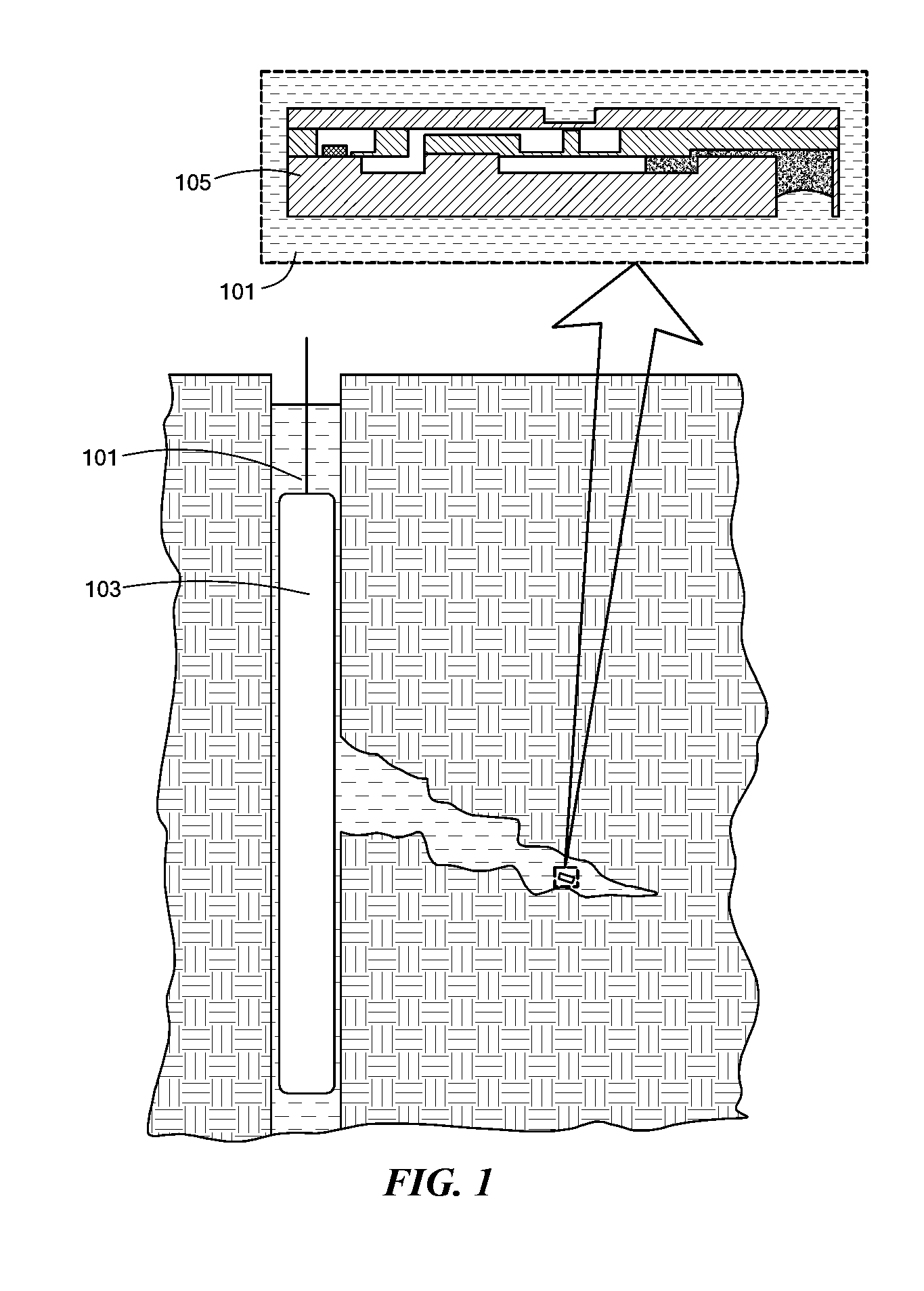
[0164]FIG. 1 shows deployment of a device 105 for use in sampling hydrocarbons during fracturing or fluid injection operations, in accordance with an embodiment of the invention. It should be noted that discussion of the specific device 105 shown, for use in sampling hydrocarbons, is for illustrative purposes only. Other device configurations and applications are within the scope of the present invention. For example, the device 105 may be deployed in a wid...


PUM

PropertyMeasurementUnit
timeaaaaaaaaaa
timeaaaaaaaaaa
timeaaaaaaaaaa

Abstract

An electrically passive device and method for in-situ acoustic emission, and/or releasing, sampling and/or measuring of a fluid or various material(s) is provided. The device may provide a robust timing mechanism to release, sample and/or perform measurements on a predefined schedule, and, in various embodiments, emits an acoustic signal sequence(s) that may be used for triangulation of the device position within, for example, a hydrocarbon reservoir or a living body.

Description

CROSS-REFERENCE TO RELATED APPLICATIONS[0001]This application is a continuation in part of U.S. application Ser. No. 13 / 760,879, filed Feb. 6, 2013, which in turn is a continuation in part of U.S. application Ser. No. 13 / 025,467, filed Feb. 11, 2011, which in turn claims priority from U.S. provisional patent application Ser. No. 61 / 337,998 filed Feb. 12, 2010, entitled “Passive Micro-vessel and Sensor.” Each of the above-described applications is hereby incorporated herein by reference, in its entirety.TECHNICAL FIELD[0002]The present invention generally relates to an electrically passive device capable of communicating its position by acoustic emission at specific time intervals, and / or of retrieving and / or sensing / and / or determining characteristics of fluid samples at, for example, specific time intervals, and / or of time-release of particles, chemical products, or pharmaceutical products. More particular embodiments of the present invention relate, for example, to an electrically ...

Claims


Application Information

Patent Timeline
Patent Type & Authority Applications(United States)
IPC IPC(8): G01N1/10
CPCG01N1/10A61B5/1455A61B5/1468A61B5/14735A61B5/155E21B47/02E21B49/081A61B2562/028A61M2005/14513A61M5/14276A61M5/14248G01N1/12G01N2001/1031A61B8/00Y10T436/2575E21B47/11
Inventor ANGELESCU, DAN E.HAUSOT, ANDREAS
Owner FLUIDION
Why Eureka
Try Eureka