System for preventing blood charring at laser beam emitting site of laser catheter
a laser catheter and laser beam technology, applied in the field of laser beam irradiation, can solve the problems of difficult continuation of laser treatment, and the use of lasers, and achieve the effect of preventing charring
- Summary
- Abstract
- Description
- Claims
- Application Information
AI Technical Summary
Benefits of technology
Problems solved by technology
Method used
Image
Examples
example 1
Observation of Changes in Erythrocyte Conditions Resulting from Laser Beam Irradiation
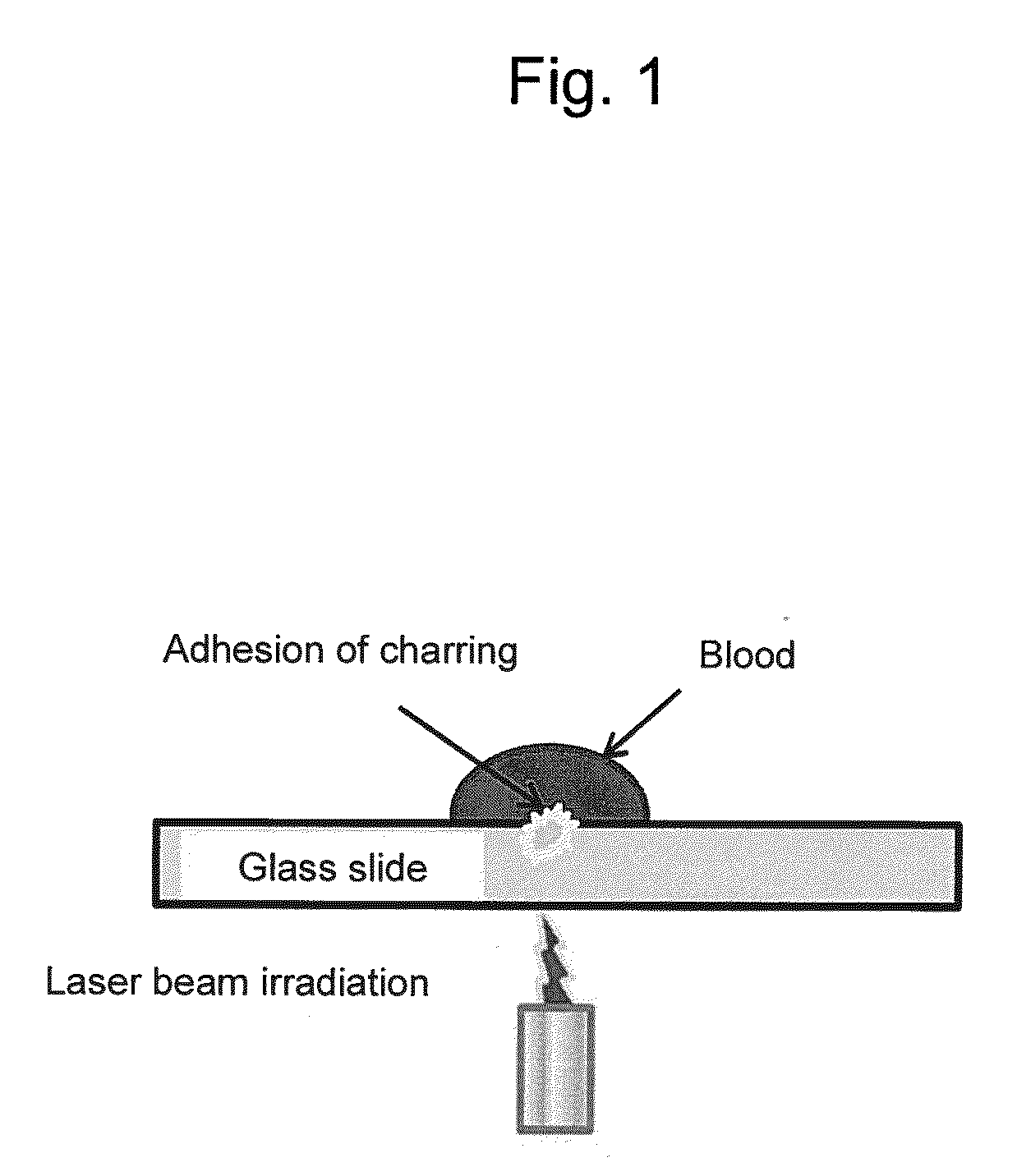
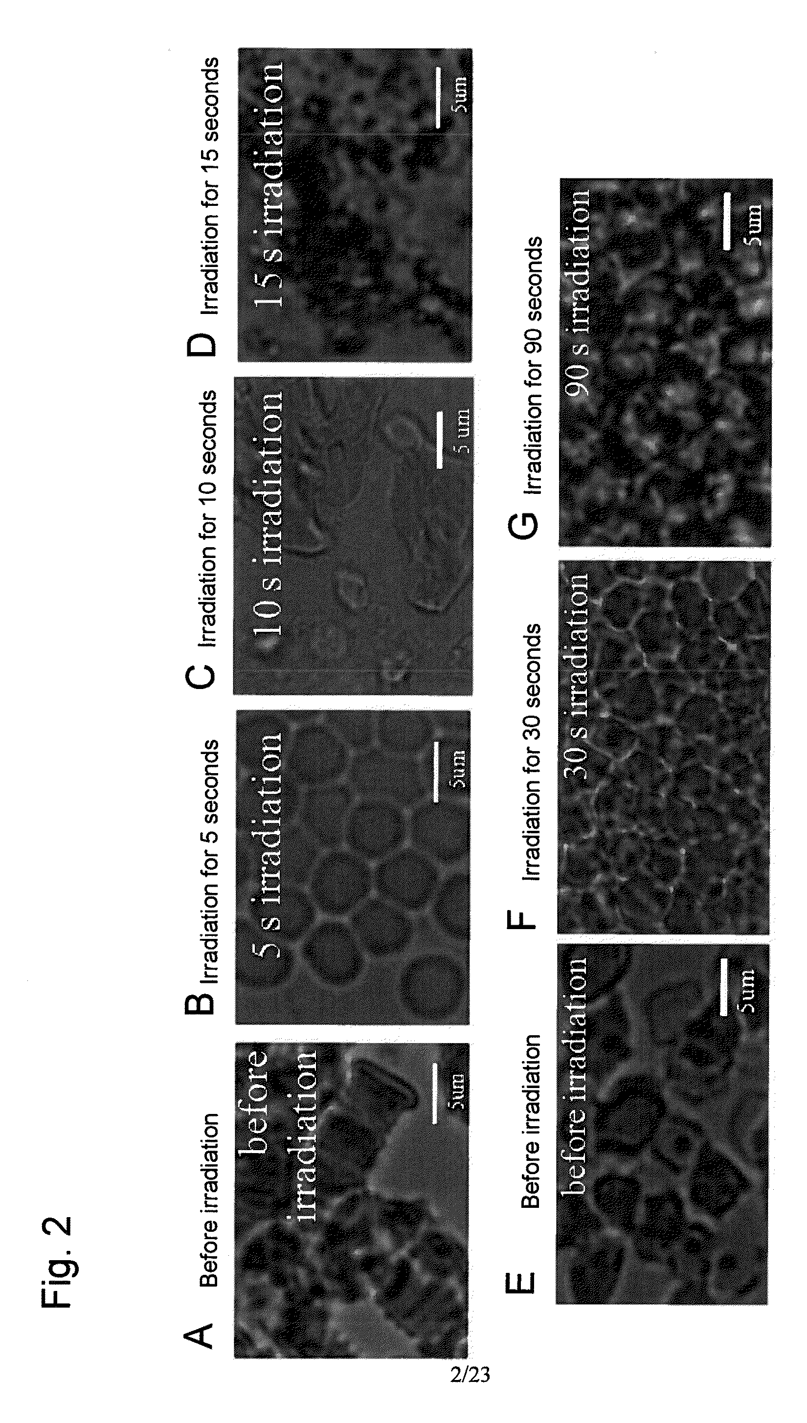
[0112]Rabbit whole blood with a hematocrit (HCT) of 40%, erythrocytes in rabbit blood, and physiological saline were mixed to prepare an erythrocyte suspension (HCT of 40%). Rabbit whole blood and the erythrocyte suspension were added dropwise to a glass slide in amounts of 5 μl each, and it was irradiated with a laser beam (663 nm; spot diameter: 5 mm; 2.3 W / cm2) to cause charring. Laser beam irradiation was stopped every 5 seconds, and the erythrocytes morphology after laser beam irradiation was observed under a microscope. The duration of laser beam irradiation was 90 seconds. The experimental system is shown in FIG. 1.
[0113]Charring occurred after 15 seconds of laser beam irradiation in the case of the whole blood. Charring did not occur after 90 seconds of laser beam irradiation in the case of the erythrocyte suspension. While erythrocytes formed a rouleaux prior to laser beam irradiation, ery...
example 2
Measurement of Changes in Reflected Light Intensity, Transmitted Light Intensity, and Temperature of Blood Models
[0114]Blood models (HCT of 40%) were prepared using venous rabbit blood, glucose, albumin, and physiological saline (Table 1).
TABLE 1Composition of plasma component modelsAlbumin (g / dl)Glucose (mg / dl)0248160∘∘∘50∘100∘∘∘∘300∘500∘∘
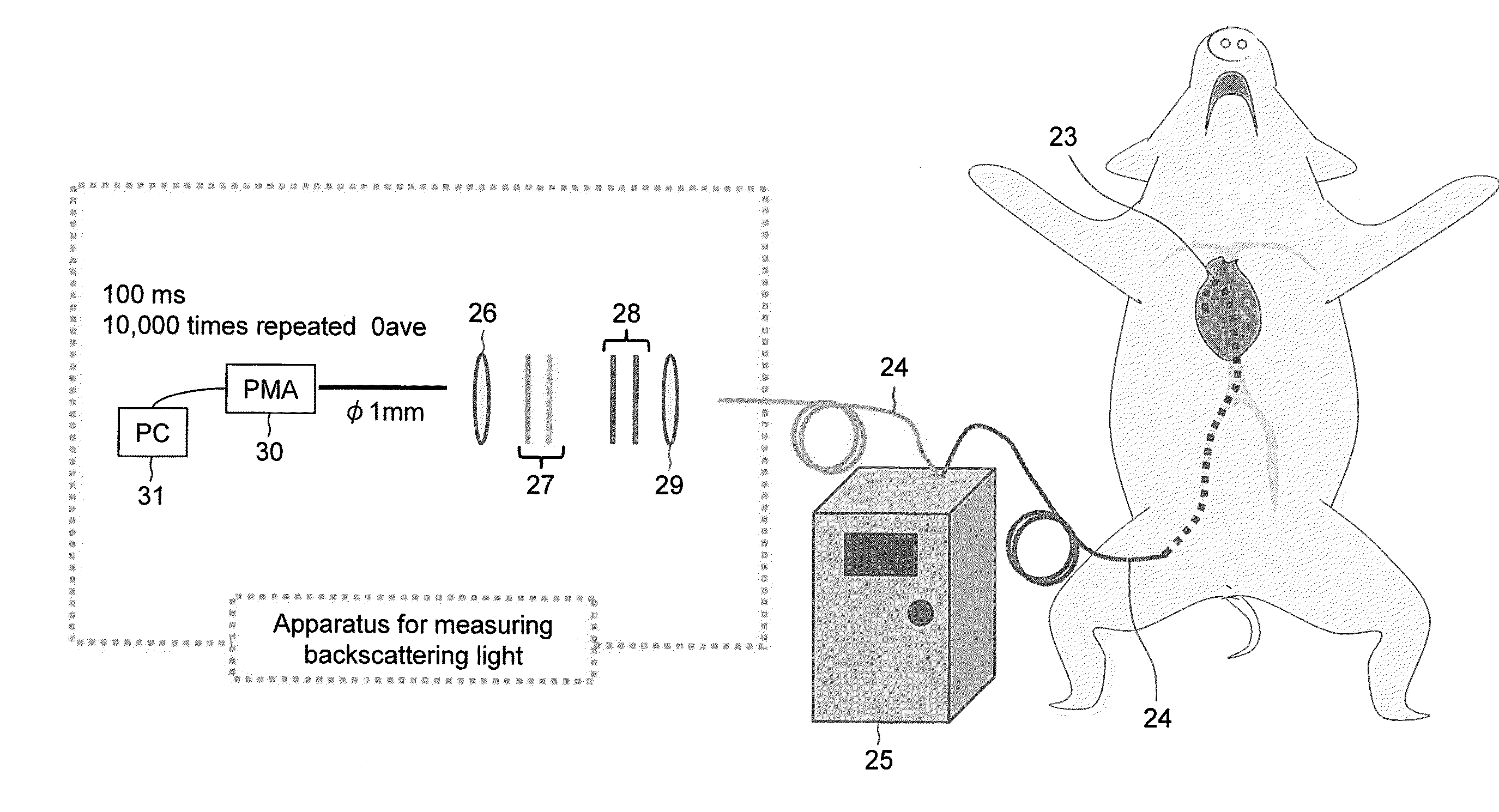
[0115]The whole blood sample and the blood model samples (50 μl each; thickness: 1 mm) were irradiated with a laser beam (663 nm; spot diameter: 517 μm; 81 W / cm2). FIG. 3 shows an apparatus used for the experiment. The reflected light intensity and the transmitted light intensity were measured with the elapse of time. Also, the reflected light intensity and temperature change at the sites irradiated with a laser beam were measured.
[0116]FIG. 4 shows changes in blood conditions of the whole blood. In FIG. 4, (a) to (d) in the upper portion show images attained by observing charring after erythrocytes were irradiated with laser for a given period of...
example 3
Control of Laser Beam Intensity in the State of Pre-Charring
[0120]A whole venous rabbit blood sample (50 μl; thickness: 1 mm) was irradiated with a laser beam (81 W / cm2). The reflected light intensity and the transmitted light intensity were measured with the elapse of time until charring occurred (i.e., a control). The laser beam intensity was reduced to 80% (64.8 W / cm2) in the state of pre-charring under which the intensity of the reflected light would decrease. The duration of laser beam irradiation was 600 to 1,000 seconds. Whether or not charring would occur when the intensity was reduced was investigated. Also, the energy of the laser beam applied was calculated and compared with the energy of the laser beam applied in the control. The blood samples used were tested (N=5). FIG. 8A schematically shows changes in the intensity of the reflected beam. In the figure, “a” indicates the reflected light intensity when laser beam irradiation is initiated, and “b” indicates the reflecte...
PUM
 Abstract
Description
Claims
Application Information
 - R&D
- Intellectual Property
- Life Sciences
- Materials
- Tech Scout
- Unparalleled Data Quality
- Higher Quality Content
- 60% Fewer Hallucinations
Browse by: Latest US Patents, China's latest patents, Technical Efficacy Thesaurus, Application Domain, Technology Topic, Popular Technical Reports.
© 2025 PatSnap. All rights reserved.Legal|Privacy policy|Modern Slavery Act Transparency Statement|Sitemap|About US| Contact US: help@patsnap.com


