
Catalyst for production of hydrogen and process for producing hydrogen using the catalyst, and catalyst for combustion of ammonia, process for producing the catalyst and process for combusting ammonia using the catalyst

a technology of catalysts and catalysts, which is applied in the direction of catalyst activation/preparation, metal/metal-hydroxide catalysts, catalysts/metal-hydroxide catalysts, etc., can solve the problems of difficult control of reaction, strong equipment dependence of hydrogen produced by such processes, and lack of convenience in the aspect of simple utilization, etc., to achieve efficient hydrogen production from ammonia, promote self-directing reaction, and cheap and practical catalysts

Inactive Publication Date: 2014-08-21
NIPPON SHOKUBAI CO LTD
View PDF3 Cites 0 Cited by
  • Summary
  • Abstract
  • Description
  • Claims
  • Application Information

AI Technical Summary

Benefits of technology

The catalyst system provides a stable and efficient process for hydrogen production from ammonia, maintaining consistent hydrogen concentration and extending catalyst lifespan by utilizing combustion heat, thus improving the quality and reliability of hydrogen fuel.

Problems solved by technology

Hydrogen produced by such processes is strongly equipment-dependent and lack of convenience in the aspect of simple utilization thereof at proper timing.
However, in the case of using these catalysts, it is difficult to control the reaction in accordance with the catalyst composition and it is not easy sometimes to steadily obtain hydrogen in a constant concentration.
Further, due to alteration of catalyst layer temperature, an ammonia reformer may possibly be damaged or the catalysts may possibly be deteriorated.
Due to these factors, the ammonia decomposition reaction becomes unstable.
If the decomposition ratio is insufficient, a large quantity of ammonia remains in the gas after the reaction and it results in provision of a fuel with an inferior quality as a hydrogen fuel.

Method used

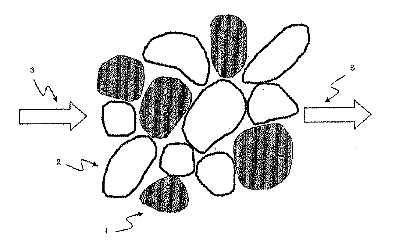
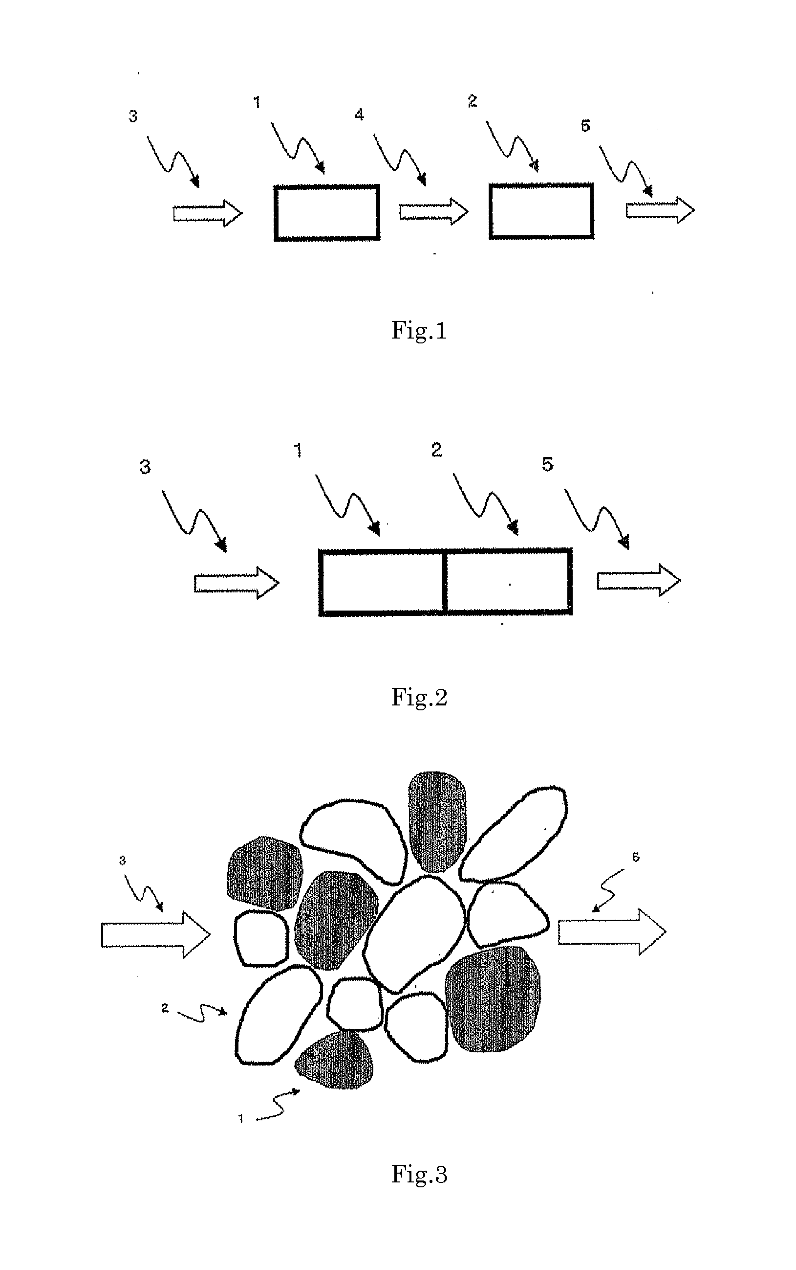
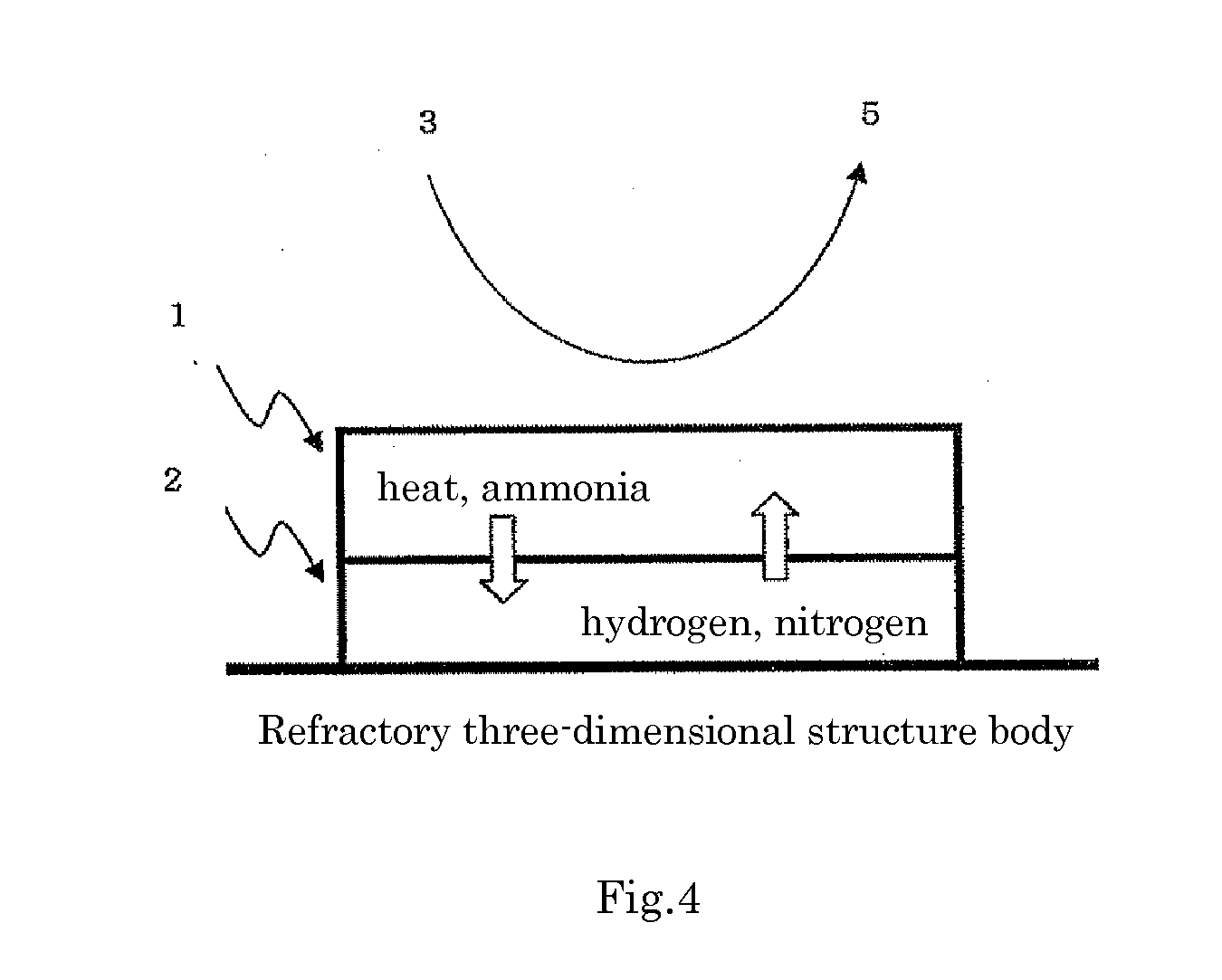

Image

  • Catalyst for production of hydrogen and process for producing hydrogen using the catalyst, and catalyst for combustion of ammonia, process for producing the catalyst and process for combusting ammonia using the catalyst
  • Catalyst for production of hydrogen and process for producing hydrogen using the catalyst, and catalyst for combustion of ammonia, process for producing the catalyst and process for combusting ammonia using the catalyst
  • Catalyst for production of hydrogen and process for producing hydrogen using the catalyst, and catalyst for combustion of ammonia, process for producing the catalyst and process for combusting ammonia using the catalyst

Examples


experimental example 1

[0113]An evenly and densely mixed manganese-cerium oxide, which is A component, was prepared by the following method, according to a solid-liquid mixing method. Powder-formed cerium carbonate and an aqueous solution of manganese nitrate were weighed and sufficiently mixed in such a manner that the content of manganese oxide in the evenly and densely mixed manganese-cerium oxide became 50% by mass in terms of MnO2, and the obtained mixture was dried at 150° C. overnight, fired at 500° C. for 5 hours and milled by a hammer mill to obtain the evenly and densely mixed manganese-cerium oxide powder. When the obtained evenly and densely mixed manganese-cerium oxide was subjected to the x-ray diffraction measurement in the condition of using a CuKα ray source, a voltage of 45 KV, a current of 40 mA, a scanning range of 10 to 90° and a scanning rate of 0.198° / minute, a main peak at the position showing the fluorite type crystal structure of cerium dioxide was detected and no crystal peak de...

experimental example 2

[0115]An aqueous solution of manganese-silver-lanthanum was prepared by adding 28.7 g of manganese nitrate hexahydrate, 4.25 g of silver nitrate and 54.1 g of lanthanum nitrate hexahydrate to 1000 mL of pure water. Next, while an aqueous TMAH solution, which was obtained by adding pure water to 1050 g of an aqueous TMAH solution of 25% by mass to dilute the solution to a liquid amount of about 3 L, being violently stirred, the aqueous solution of manganese-silver-lanthanum was slowly added dropwise thereto. On completion of the dropwise addition, the mixture was continuously stirred for about 30 minutes for aging. After the aging, the obtained precipitate was filtered, washed with pure water and thereafter dried at 110° C. The dried material was pulverized, and thereafter fired at 400° C. for 1 hour and further fired at 650° C. for 2 hours in atmospheric air to obtain a manganese-silver-lanthanum composite oxide (catalyst 2). When the catalyst 2 was subjected to the x-ray diffractio...

experimental example 3

[0116]A cerium carbonate powder in an amount of 19.6 g was added to an aqueous solution obtained by dissolving 6.6 g of manganese nitrate hexahydrate, 25.4 g of cobalt nitrate hexahydrate and 1.47 g of silver nitrate in distilled water. Next, the mixture was heated while being stirred by a hot stirrer for evaporating water therein to obtain a dried solid. The dried solid was dried at 150° C. overnight and thereafter, pulverized, and fired at 500° C. for 2 hours in atmospheric air to obtain a cobalt-silver-manganese-cerium oxide powder (catalyst 3). When the catalyst 3 was subjected to the x-ray diffraction measurement in the same conditions as those of Experimental Example 1, it was found that merely a peak showing the fluorite type crystal structure of cerium dioxide and a peak showing the structure of tricobalt tetroxide were detected, and no crystal peaks derived from silver and manganese were observed. Therefore, it was confirmed that manganese existed in the form of an evenly a...


PUM

PropertyMeasurementUnit
temperatureaaaaaaaaaa
molar ratioaaaaaaaaaa
temperatureaaaaaaaaaa

Abstract

Disclosed is a catalyst which can be used in the process for producing hydrogen by decomposing ammonia, can generate heat efficiently in the interior of a reactor without requiring excessive heating the reactor externally, and can decompose ammonia efficiently and steadily by utilizing the heat to produce hydrogen. Also disclosed is a technique for producing hydrogen by decomposing ammonia efficiently utilizing the catalyst. Specifically disclosed is a catalyst for use in the production of hydrogen, which is characterized by comprising an ammonia-combusting catalytic component and an ammonia-decomposing catalytic component. Also specifically disclosed is a catalyst for use in the production of hydrogen, which is characterized by comprising at least one metal element selected from the group consisting of cobalt, iron, nickel and molybdenum.

Description

TECHNICAL FIELD[0001]The present invention relates to a catalyst used for producing hydrogen using ammonia as a raw material and a process for producing hydrogen using the catalyst. The present invention also relates to a catalyst used for combusting ammonia existing in air or high concentration ammonia contained in an industrial waste gas, etc. at low temperature, a process for producing the catalyst and a process for combusting ammonia using the catalyst.BACKGROUND ART[0002]With respect to techniques for production of hydrogen, there are by-product hydrogen from other industrial processes, e.g., from processes manufacturing iron and steel, hydrogen produced by reforming coal and petroleum, etc. Hydrogen produced by such processes is strongly equipment-dependent and lack of convenience in the aspect of simple utilization thereof at proper timing.[0003]On the other hand, as a means for easily obtaining hydrogen, there is a method of utilizing a decomposition reaction of ammonia. The...

Claims


Application Information

Patent Timeline
Patent Type & Authority Applications(United States)
IPC IPC(8): B01J23/83C01B3/06
CPCC01B3/06B01J23/83B01J21/04B01J23/002B01J23/34B01J23/42B01J23/44B01J23/50B01J23/688B01J23/882B01J23/8892B01J23/8986B01J37/0201B01J37/031B01J2523/00C01B3/047C01B2203/1041C01B2203/1047C01B2203/1058Y02E60/36B01J35/19B01J35/613B01J35/733B01J2235/15B01J2523/17B01J2523/3712B01J2523/72B01J2523/845B01J2523/18B01J2523/847B01J2523/3706B01J23/40B01J23/74B01J23/78B01J23/88B01J35/30
Inventor OKAMURA, JUNJIYOSHIMUNE, MASANORIKIRISHIKI, MASARUTSUNEKI, HIDEAKI
Owner NIPPON SHOKUBAI CO LTD
Learn More