
Inorganic particle scattering film having a good light-extraction performance

a technology of organic particles and scattering films, which is applied in the direction of sustainable manufacturing/processing, instruments, and final product manufacturing, etc., can solve the problems of optical power reflection loss, limited application range, and harmful effect on the electric field of devices, etc., and achieve excellent light extraction effect, flatness and hardness.

Inactive Publication Date: 2014-08-21
LTC
View PDF7 Cites 22 Cited by
  • Summary
  • Abstract
  • Description
  • Claims
  • Application Information

AI Technical Summary

Benefits of technology

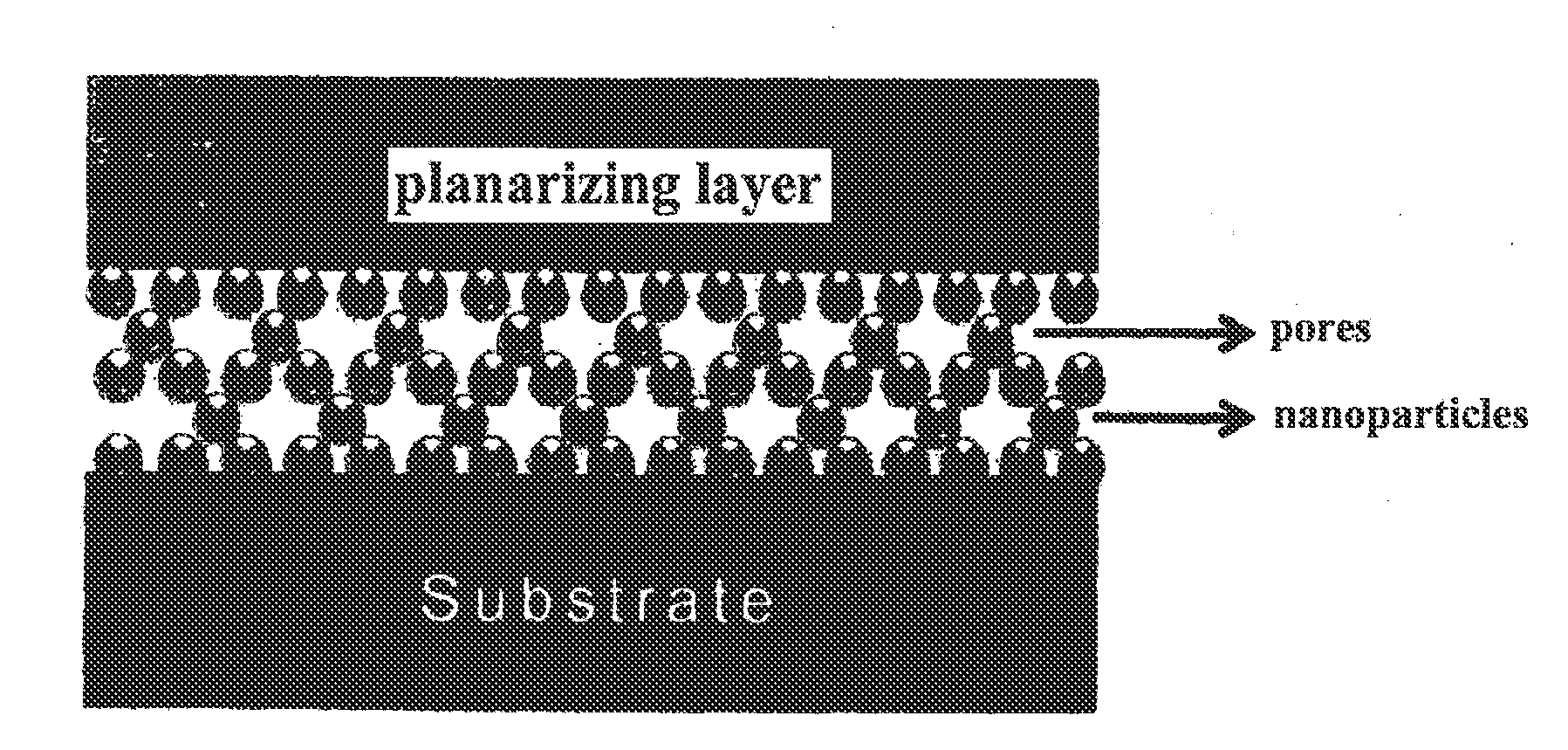
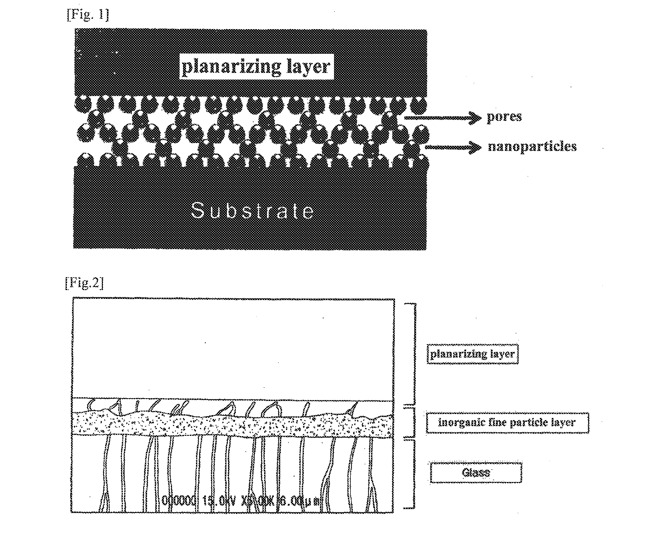
The present invention provides an inorganic fine particle scattering film that has improved light extraction, is flat and hard, and can be used in various fields such as image display devices, lighting elements, and solar cells. The film has a layer with pores that scatter light and a planarizing layer to protect and planarize the layer.

Problems solved by technology

In the case of a light emitting device, when light is emitted, reflection loss occurs in optical power due a difference in a refractive index on a light emitting device interface.
However, it is expected that such a structure formed with surface unevenness, in electrode configuration on a scattering layer surface, finally has a harmful effect on the electric field of a device.
Thus, it has a limitation in its application range.
However, in the case where inorganic particles having a different refractive index from that of an organic binder are introduced into the organic binder, since a difference between the organic binder and the inorganic particles in the refractive index is not large, a scattering effect is not high.
Thus, there is a problem in that a light extraction effect may be halved.
Herein, in the case of a resin used for this method, in use for a long time, a reduction in luminous efficiency may be caused due to discoloration or the like by moisture.
Also, a resin used as organic backfill has a low refractive index (n=1.4 to 1.5), and thus has a problem in that its scattering effect cannot be further improved.
However, such a scattering glass plate has a problem in that it cannot be directly applied on a light emitting device surface in its process, and is not suitable for employment in various shapes and forms of substrates in view of its process.

Method used


Image

  • Inorganic particle scattering film having a good light-extraction performance
  • Inorganic particle scattering film having a good light-extraction performance
  • Inorganic particle scattering film having a good light-extraction performance

Examples


example 1-1

[0103]12.5 wt % of ZrOCl3.8H2O and 2 wt % of Y (NO3)3.6H2O were dissolved in water, and reacted with a mixture liquid of Ammonium hydroxide (NH4OH) to prepare a solution (precipitated at pH=9.00). After the prepared precipitated solution was reacted for 1 hour at room temperature, the reaction was completed. Precipitates and solution were separated through a filtering step, and the separated precipitates were dispersed in and washed with distilled water, and were dehydrated through a filter with pores of 1 μm, followed by repetitive washing. The dehydrated precipitates were dried in a dryer at 100° C. for 24 hours, and subjected to heat treatment in an electric furnace under an air atmosphere, at 800° C. for 1 hour.

[0104]The above described process is shown in FIG. 4. Also, on synthesized nano powder, the x-ray diffraction result and the scanning electron microscopic (SEM) photograph are shown in FIGS. 5 and 6, respectively.

example 1-2

[0105]12.5 wt % of ZrOCl3.8H2O and 2 wt % of Y(NO3)3.6H2O were dissolved in distilled water comprising additives, and reacted with a mixture liquid of Amonium hydroxide (NH4OH) to prepare a solution (precipitated at pH=9.00). After the prepared precipitated solution was reacted for 1 hour at room temperature, and then reacted at a reaction temperature raised up to 60° C. for 3 hours, the reaction was completed. From then, the same process as that in Example 1-1 was performed. On synthesized nano powder, the x-ray diffraction result and the scanning electron microscopic (SEM) photograph are shown in FIGS. 5 and 7, respectively.

example 1-3

[0106]This process was performed in the same manner as described in Example 1-2, except that additives are dropped to a zirconia aqueous solution and a yttria aqueous solution. After the resultant solution was reacted for 1 hour at room temperature, and then further reacted at a reaction temperature raised up to 60° C. for 3 hours. From then, the same process as that in Example 1-1 was performed. The particles obtained from this method had a smaller size than those in Example 1-2.

[0107]From the result, it can be seen that YSZ powder prepared in Example 1-1 showed a more developed crystallinity (see FIG. 5).

[0108]Through the transmission electron microscopic (TEM) photograph of YSZ particles prepared in Example 1-1, it was possible to confirm the shape and size of the particles. It was found that the particle size ranges 50 to 60 nm through the transmission electron microscopic photograph. The result is shown in FIG. 8.


PUM

PropertyMeasurementUnit
Thicknessaaaaaaaaaa
Thicknessaaaaaaaaaa
Nanoscale particle sizeaaaaaaaaaa

Abstract

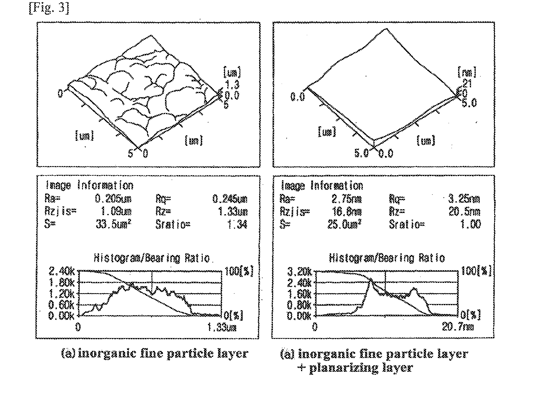
Disclosed are an inorganic fine particle scattering film and a manufacturing method thereof, wherein an inorganic fine particle layer comprising pores is formed on a light emitting device interface or a transparent substrate so as to achieve a high light extraction effect through a light scattering effect, and a planarizing layer is formed on the inorganic fine particle layer so as to show a high flatness and a high hardness. The disclosed inorganic fine particle scattering film is excellent in a light extraction effect, flatness and hardness and thus can be applied in the various fields such as an image display device, a lighting element, a solar cell.

Description

FIELD OF THE INVENTION[0001]The present invention relates to an inorganic fine particle scattering film and a manufacturing method thereof, wherein an inorganic fine particle layer comprising pores is formed on a light emitting device interface or a transparent substrate so as to achieve a high light extraction effect through a light scattering effect, and a planarizing layer is formed on the inorganic fine particle layer so as to show a high flatness and a high hardness.DESCRIPTION OF THE PRIOR ART[0002]In the case of a light emitting device, when light is emitted, reflection loss occurs in optical power due a difference in a refractive index on a light emitting device interface. Till now, a method of forming an anti-reflective film on a surface or a transparent substrate in order to increase the optical power of the light emitting device, or a method of increasing the optical power through scattering by forming unevenness through etching on a surface have been researched and devel...

Claims


Application Information

Patent Timeline
IPC IPC(8): G02B5/02
CPCG02B5/0268G02B5/0294C01G25/00C01P2002/72C01P2004/03C01P2004/04C01P2004/64B82Y30/00H01L2933/0091Y10T428/24364Y02E10/549Y02P70/50H01L21/7684H10K71/12H10K50/854
Inventor RYU, KWANG HYUNKIM, HWA YOUNGKIM, SUNG KOOKLEEMIN, SUNG HWAN
Owner LTC
Learn More