
Sintered alloy and manufacturing method thereof

Active Publication Date: 2014-09-04
RESONAC CORP
View PDF4 Cites 4 Cited by
  • Summary
  • Abstract
  • Description
  • Claims
  • Application Information

AI Technical Summary

Benefits of technology

The present invention provides a sintered alloy that has excellent heat resistance, wear resistance, and corrosion resistance against salt damage in cold districts. The alloy consists of two kinds of phases: one containing larger dispersed carbide and having heat resistance and corrosion resistance, and the other containing smaller dispersed carbide and having heat resistance and corrosion resistance. The smaller carbide dispersed in the larger phase enhances wear resistance and reduces abrasion of the opponent component, while also contributing to wear resistance by preventing plastic flow. The alloy also contains nickel and copper to enhance heat resistance and corrosion resistance, and copper or copper powder to enhance corrosion resistance. The alloy has a metallic structure with the phase A dispersed in the phase B randomly, and allows for excellent heat resistance, corrosion resistance, wear resistance, and machinability. It is suitable for use in turbo components for turbocharger and can simplify component design against chloride ion and salt damage.

Problems solved by technology

However, since the sintered component disclosed in Patent document No. 1 is formed through liquid phase-sintering, the sintered component may be machined as the case of severe dimensional accuracy.
Since the large amount of hard carbide is precipitated in the sintered component, the machinability of the sintered component is not good and thus required to be improved.
In this case, since the thermal expansion coefficient of the turbo component is different from those of the adjacent components, some spaces are formed between the turbo component and the adjacent components, causing the insufficient connections between the turbo component and the adjacent components and rendering component design available in the turbocharger difficult.
A large amount of chloride ion contained in the high concentration salt water breaks the passive film formed at the surface of stainless steel and causes the corrosion against the stainless steel.
Therefore, when the heat resistant bearings for turbo charger are made of the stainless steel, some corrosion problems such as salt damage are caused.

Method used


Image

  • Sintered alloy and manufacturing method thereof
  • Sintered alloy and manufacturing method thereof
  • Sintered alloy and manufacturing method thereof

Examples


example 1

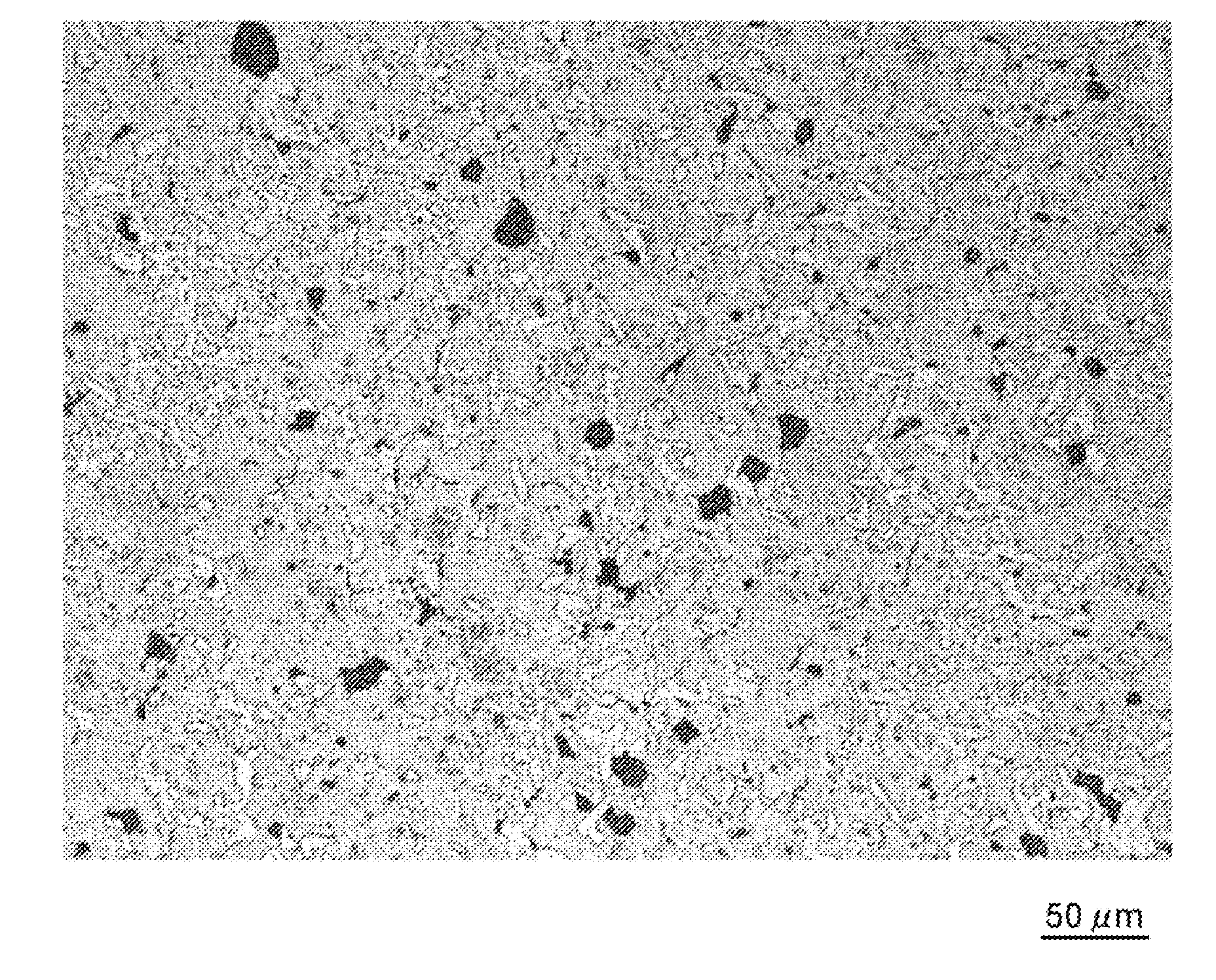
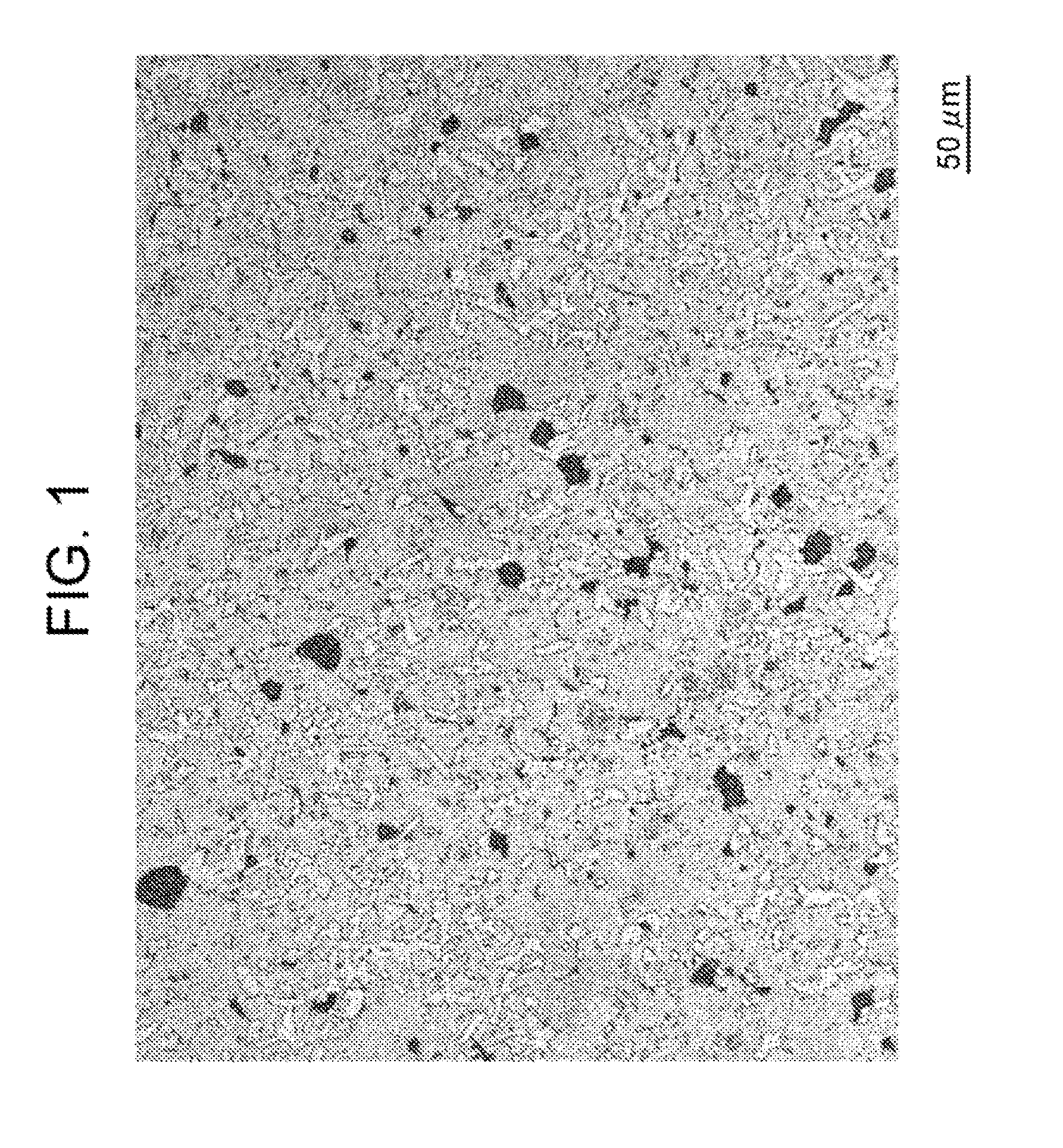
[0072]The iron alloy powder A including, in percentage by mass, Cr: 34, Ni: 10, Si: 2, C: 2 and the balance of Fe plus unavoidable impurities, the iron alloy powder B including, in percentage by mass, Cr: 18, Ni: 8 and the balance of Fe plus unavoidable impurities, the iron-phosphorus powder including, in percentage by mass, P: 20 and the balance of Fe plus unavoidable impurities, the nickel powder, the copper powder and the graphite powder were prepared and mixed with one another at the ratios shown in Table 1 to blend the raw material powder. The raw material powders were compressed respectively in the shape of pillar with an outer diameter of 10 mm and a height of 10 mm, in the shape of square pillar with a length of 26 mm, a width of ii mm and a height of 8 mm, and in the shape of thin plate with an outer diameter of 24 mm and a height of 8 mm, and then sintered at a temperature of 1100° C. under vacuum atmosphere to form sintered samples indicated by numbers of 01 to 11. The co...

example 2

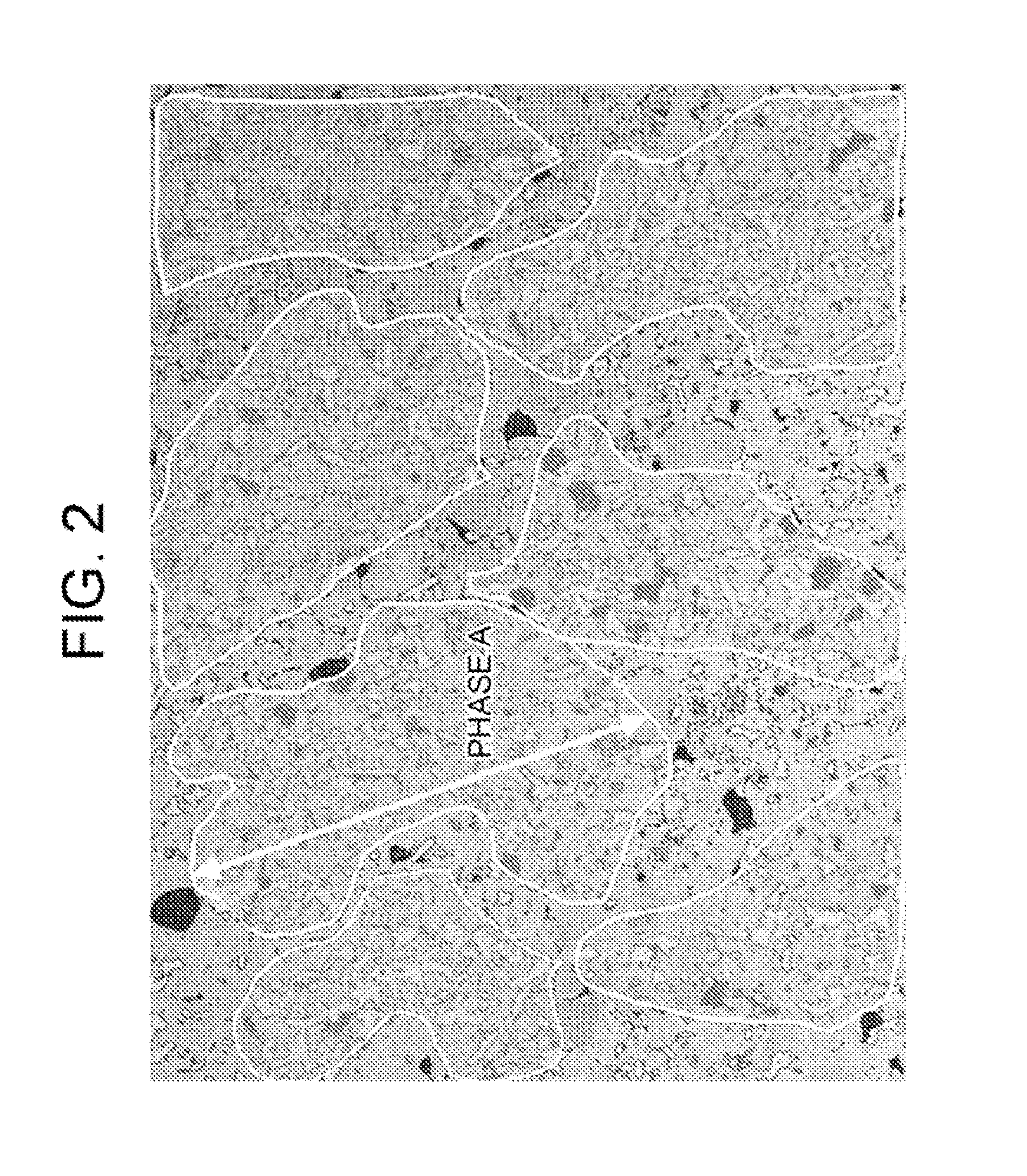
[0085]The iron alloy powders A having the respective components shown in Table 3 were prepared, and mixed with the iron alloy powder B, the iron-phosphorus alloy powder, the nickel powder, the copper powder and the graphite powder which were used in Example 1 at the ratios shown in Table 3 to blend the respective raw material powders. The thus obtained raw material powders were compressed and sintered respectively in the same manner as in Example 1 to form sintered samples 12 to 30 in the shape of pillar, in the shape of square pillar and in the shape of thin plate. The total components of the sintered samples were listed in Table 3. With respect to the sintered samples, the average particle diameter of carbide in the phase A and the phase B, the ratio of the phase A, the maximum dimension of the phase A, the thermal expansion coefficient, the increase in weight after oxidizing test, the corrosion area ratio and the abrasion depth after roll-on-disc abrasion test were measured in th...

example 3

[0100]The iron alloy powders B having the respective compositions shown in Table 5 were prepared, and mixed with the iron alloy powder A, the iron-phosphorus alloy powder, the nickel powder, the copper powder and the graphite powder which were used in Example 1 at the ratios shown in Table 5 to blend the respective raw material powders. The thus obtained raw material powders were compressed and sintered in the same manner as in Example 1 to form sintered samples 31 to 41 in the shape of pillar, in the square pillar and in the shape of thin plate. The compositions of the sintered samples were listed in Table 5. With respect to the sintered samples, the average particle diameter of carbide in the phase A and the phase B, the ratio of the phase A, the maximum dimension of the phase A, the thermal expansion coefficients, the increases in weight after oxidizing test, the corrosion area ratio and the abrasion depth after roll-on-disc abrasion test were measured in the same manner as in Ex...


PUM

PropertyMeasurementUnit
Temperatureaaaaaaaaaa
Lengthaaaaaaaaaa
Lengthaaaaaaaaaa

Abstract

A sintered alloy includes, in percentage by mass, Cr: 10.37 to 39.73, Ni: 5.10 to 24.89, Si: 0.14 to 2.52, Cu: 1.0 to 10.0, P: 0.1 to 1.5, C: 0.18 to 3.20 and the balance of Fe plus unavoidable impurities; a phase A containing precipitated metallic carbide with an average particle diameter of 10 to 50 μm; and a phase B containing precipitated metallic carbide with an average particle diameter of 10 μm or less, wherein the phase A is randomly dispersed in the phase B and the average particle diameter DA of the precipitated metallic carbide in the phase A is larger than the average particle diameter DB of the precipitated metallic carbide of the phase B.

Description

CROSS-REFERENCE TO RELATED APPLICATIONS[0001]This application is based upon and claims the benefit of priority from the prior Japanese Patent Application No. 2013-040686 filed on Mar. 1, 2013; the entire contents which are incorporated herein by reference.BACKGROUND[0002]1. Field of the Invention[0003]The present invention relates to a sintered alloy which is suitable for a turbo component for turbocharger, particularly a heat resistant bearing and the like which require heat resistance, corrosion resistance and wear resistance, and a method for manufacturing the sintered alloy.[0004]2. Background of the Invention[0005]Generally, in a turbocharger provided in an internal combustion engine, a turbine is rotatably supported by a turbine housing connected with an exhaust manifold of the internal combustion engine. An exhaust gas flowed in the turbine housing is flowed in the turbine from the outside thereof and emitted in the axial direction thereof while the turbine is rotated. Then, ...

Claims


Application Information

Patent Timeline
IPC IPC(8): F01D25/16B22F5/10B22F3/12
CPCF01D25/16B22F5/10B22F3/12C22C33/0207C22C33/0285C22C38/002C22C38/02C22C38/34C22C38/42C22C38/56B22F5/009B22F2998/10B22F3/02B22F3/10
Inventor FUKAE, DAISUKEKAWATA, HIDEAKI
Owner RESONAC CORP
Features
  • Generate Ideas
  • Intellectual Property
  • Life Sciences
  • Materials
  • Tech Scout
  • Unparalleled Data Quality
  • Higher Quality Content
  • 60% Fewer Hallucinations
Learn More