System and Method for Treating Water Systems with High Voltage Discharge and Ozone

a technology of high-voltage discharge and water system, which is applied in the nature of treatment water, energy-based wastewater treatment, and refining by electric/magnetic means, etc. it can solve the problems of severely limiting the applicability of the existing prior art, utilizing an electromagnetic or electrolysis system that captures excess energy, and avoiding damage effects. , to achieve the effect of limiting the applicability, avoiding damage, and beneficial effect of water treatmen

Active Publication Date: 2014-11-06
NCH CORP
View PDF0 Cites 28 Cited by
  • Summary
  • Abstract
  • Description
  • Claims
  • Application Information

AI Technical Summary

Benefits of technology

[0013]This invention relates to a system and method using non-chemical technologies to treat flowing water systems, such as cooling towers and closed-loop or recirculating water systems. This treatment involves generating a high frequency and high voltage discharge between two electrodes submerged in the water being treated. With each discharge between the electrodes there is a number of long lived oxidative chemicals (ozone, hydrogen peroxide) and short lived oxidative chemicals (super oxides, hydroxyl radicals, and hydrogen radicals) generated, UV radiation is also generated, together with sonic shockwaves. These effects are well known in the prior art. However, it is not previously known to utilize an electromagnetic or electrolysis system that captures the excess energy produced by the high voltage discharge (which is normally wasted). According to one embodiment of the invention, the system uses this excess energy to further condition and treat the water by allowing the current to flow through wire loops connecting water system piping to a ground to generate a magnetic field in the water. This magnetic field has been shown to have a beneficial effect in water treatment and avoids the damaging effects of the large amounts of electromagnetic radiation throughout the entire water system have on the electronic control systems used to measure conductivity, pH, biological activity, as well as to control pumps and other critical system

Problems solved by technology

However, it is not previously known to utilize an electromagnetic or electrolysis system that captures the excess energy produced by the high voltage discharge (which is normally wasted).
To use

Method used


Image

  • System and Method for Treating Water Systems with High Voltage Discharge and Ozone
  • System and Method for Treating Water Systems with High Voltage Discharge and Ozone
  • System and Method for Treating Water Systems with High Voltage Discharge and Ozone

Examples


example 1a

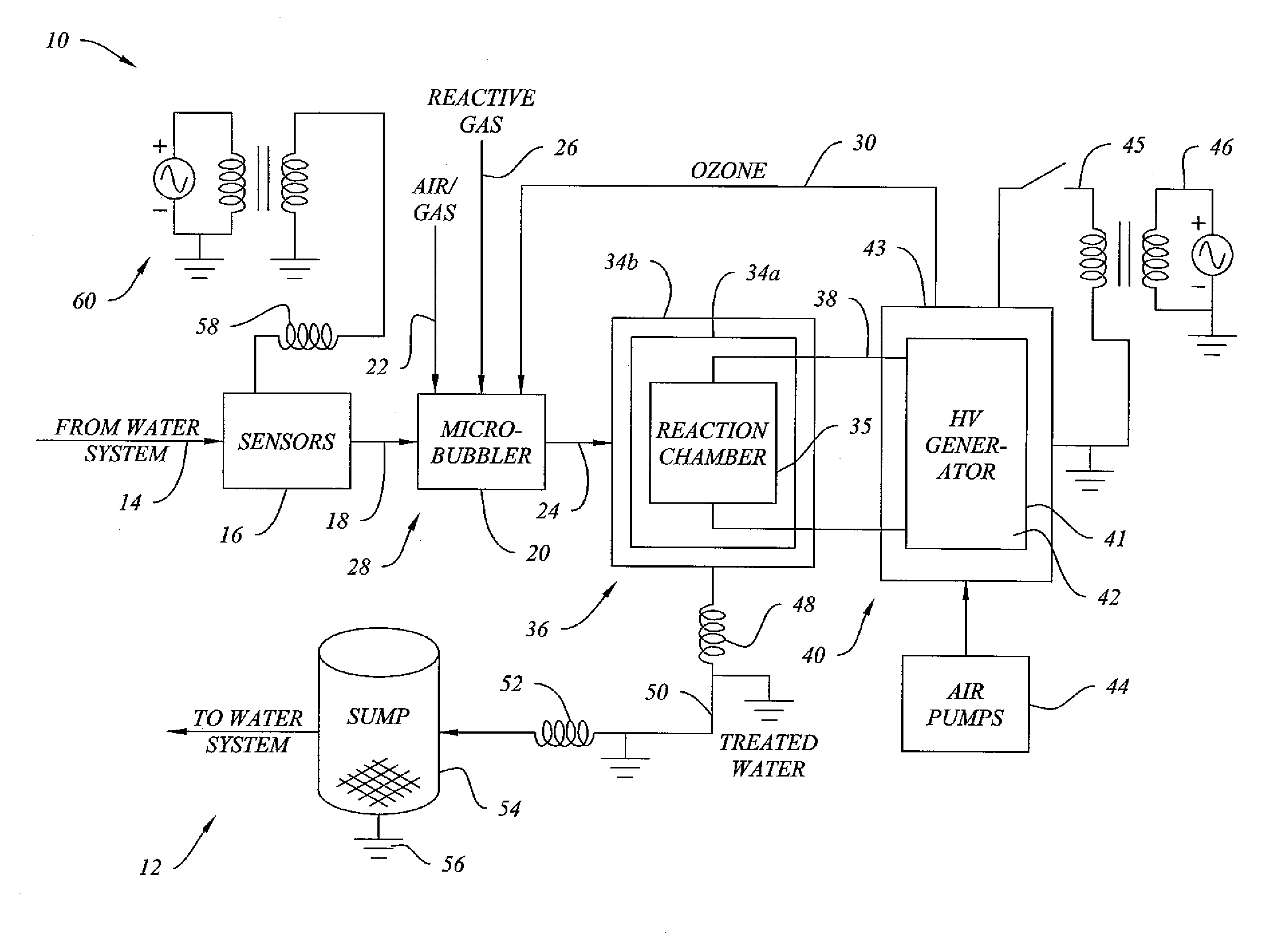
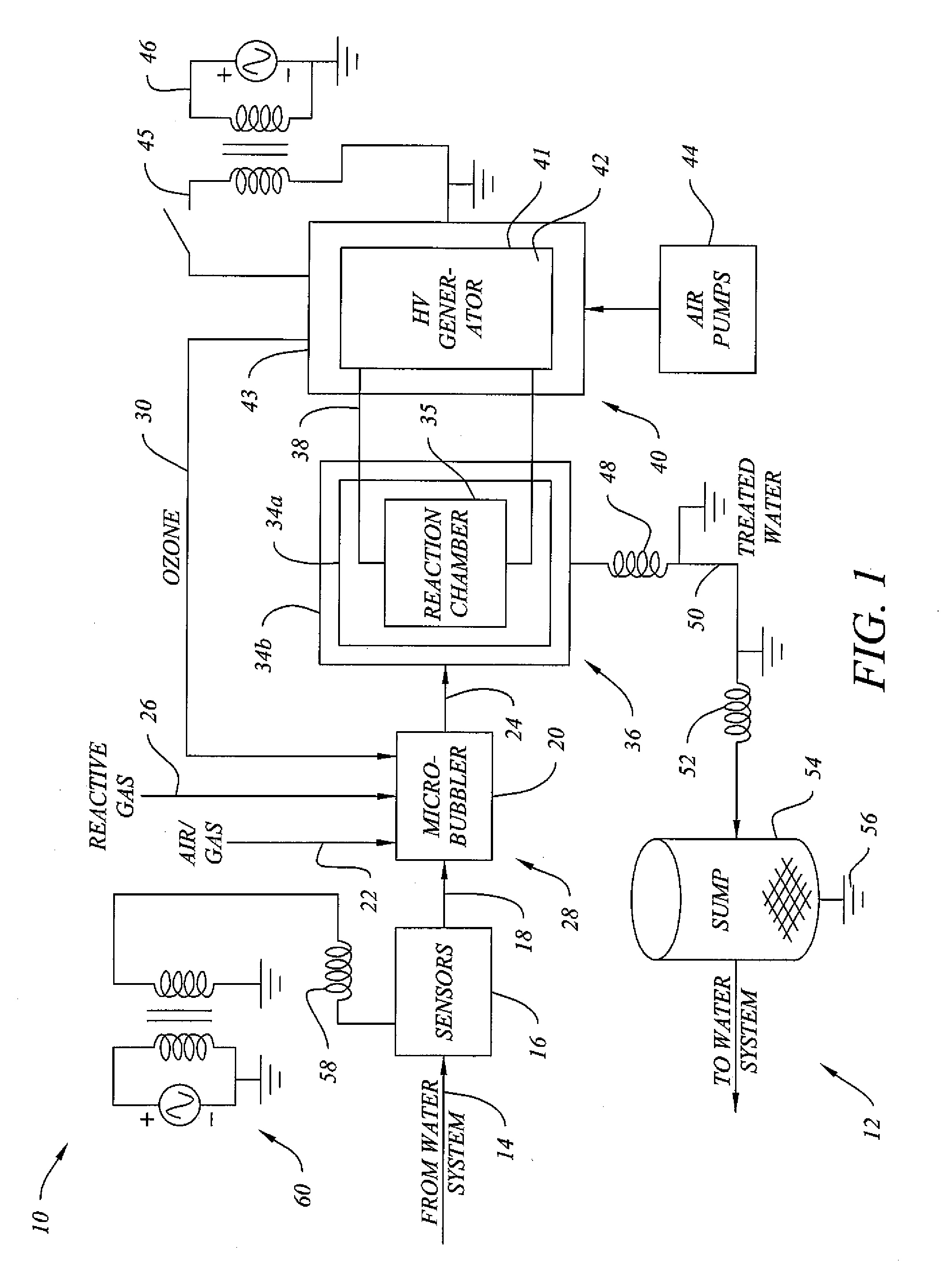
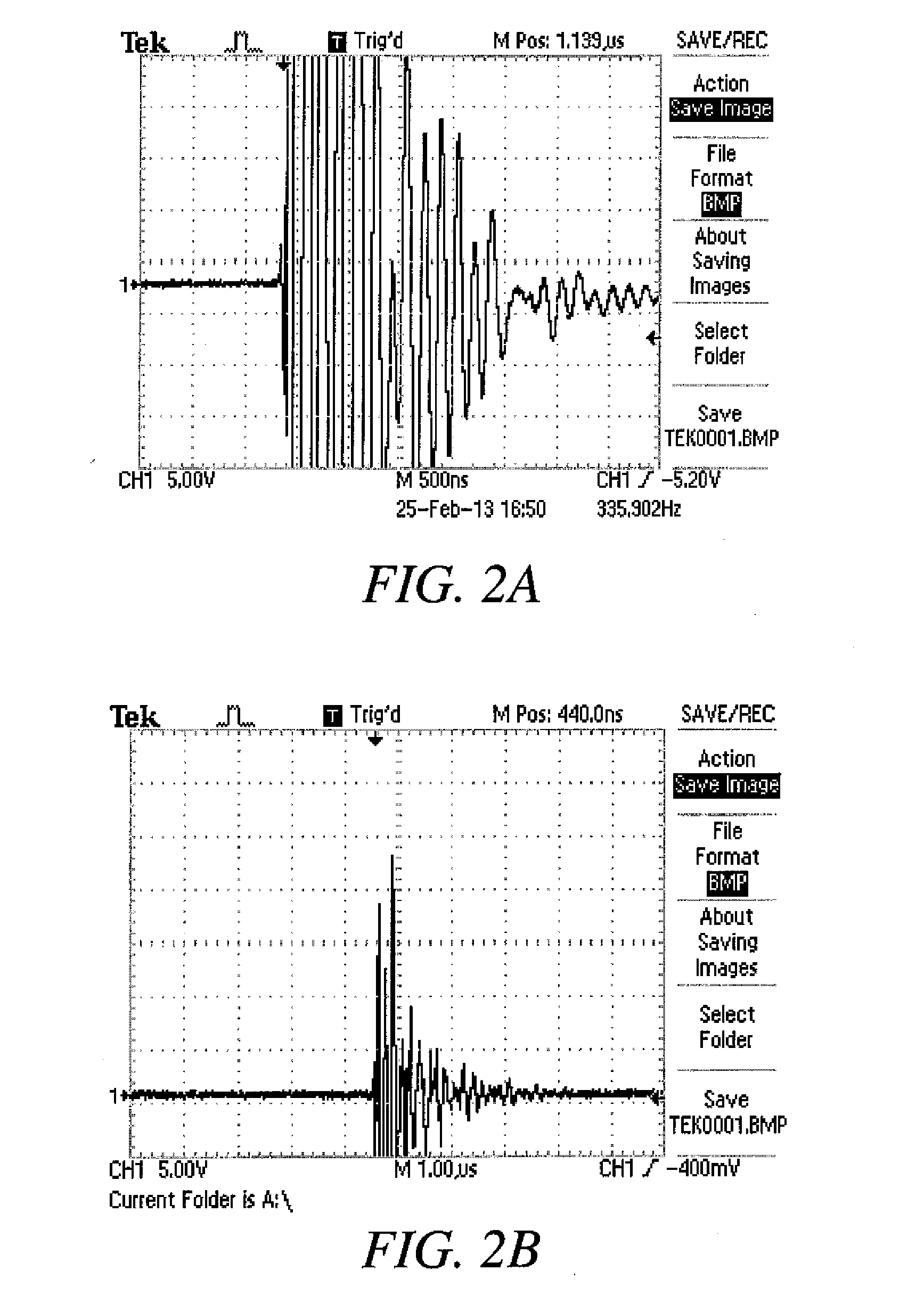
[0031]Direct discharge into an unprotected system: In the first set of experiments, a pilot cooling tower was used. Components of this experimental system that correspond with the systems depicted in FIG. 1 are labeled according to the reference numbers in FIG. 1. A cooling tower (total volume 100 L) water system 12 was charged with water and the system was set to circulate. The water chemistry was monitored using an Advantage Control system and biological monitoring as performed using two in-house biological monitoring systems and a ChemTrak biological monitor. These systems are typically found or are similar to those typically found in larger scale commercial or industrial cooling tower operations. To incorporate the high voltage generator system into the cooling tower, a side-stream flow (stream 18) was pulled from the heat exchanger rack via a mechanical ball valve and 12 feet of 0.75 inch diameter clear flexible PVC tubing. This valve allows the system to change flow dynamics b...

example 1b

[0033]Direct discharge into a protected system: The experiment of 1A was repeated, but with a multiple ground protective system in place. Grounds were placed in a sump 54 and parts of the tubing (using a screw and wire wrapping as discussed above) throughout system. FIG. 3 shows that there is a significant reduction in the electromagnetic field in the water. Using the multiple ground system, it is now possible to run the high voltage discharge system for several hours continuously without causing problems to the electronic control and monitoring equipment used as part of the water system 12.

example 2

[0034]Bench Trials for Removal of Microorganisms: Four bench-level studies were conducted to determine the efficacy of a non-thermal plasma discharge in water to inactivate microorganisms. It is known that a plasma discharge in water will generate active oxygen species, UV radiation, and pressure field shock waves all of which can inactivate microorganisms. A plasma discharge can be achieved by increasing the electric field in a solution beyond its breakdown voltage. The breakdown voltage is dependent on the conductivity and the dielectric properties of the solution. It has been observed that a relationship exists between the input energy and the log reduction of the microorganisms in the system. It has also been documented that the input energy needed to achieve a one log reduction (known as D-value) in E. coli can vary from 14 J / L to greater than 366 J / L. As for experiments with certain species of pseudomonas, it has been reported that 85 kJ / L is the average input energy needed to...


PUM

PropertyMeasurementUnit
Electric potential / voltageaaaaaaaaaa
Frequencyaaaaaaaaaa

Abstract

A system and method for treating flowing water systems with a plasma discharge to remove or control growth of microbiological species. The system and method protect other components of the water system from being damaged by excess energy from the electrohydraulic treatment. The system and method also recycle ozone gas generated by a high voltage generator that powers the plasma discharge to further treat the water. A gas infusion system upstream of or inside a plasma reaction chamber may be used to create fine bubbles of ozone, air, or other gases in the water being treated to aid in plasma generation.

Description

CROSS-REFERENCE TO RELATED APPLICATIONS[0001]This application claims the benefit of provisional U.S. Application Ser. No. 61 / 818,229, filed on May 1, 2013.BACKGROUND OF THE INVENTION[0002]1. Field of the Invention[0003]This invention relates to a system and method for treating flowing water systems using a high voltage discharge to generate plasma and using the ozone by-product from the high voltage generation, particularly useful in treating cooling tower or other recirculating or closed-loop systems.[0004]2. Description of Related Art[0005]Anthropogenic water systems are critical components commonly found in most of the world's energy producing facilities, industrial and manufacturing plants, hospitals, and other institutional complexes and buildings. These systems consume around 700 billion gallons of water annually with a cost of $1.8 billion in make-up water and sewage handling costs alone. All of these anthropogenic water systems require some form of treatment, either chemical...

Claims


Application Information

Patent Timeline
IPC IPC(8): C02F1/467C02F1/46
CPCC02F1/4608C02F1/4672C02F2201/46135C02F2201/4615C02F2201/46175C02F1/32C02F1/34C02F1/36C02F1/487C02F1/78C02F2103/023C02F2303/04C02F2303/10C02F2303/26C02F2305/023C02F2201/483Y02W10/30
Inventor DENVIR, ADRIAN J.VELA, DAVID F.HOLLOWAY, MATT M.
Owner NCH CORP
Why Eureka
Try Eureka