Inorganic filler, and insulating resin composition, insulating film, prepreg and printed circuit board including the same

Inactive Publication Date: 2015-01-29
SAMSUNG ELECTRO MECHANICS CO LTD
View PDF4 Cites 11 Cited by
  • Summary
  • Abstract
  • Description
  • Claims
  • Application Information

AI Technical Summary

Benefits of technology

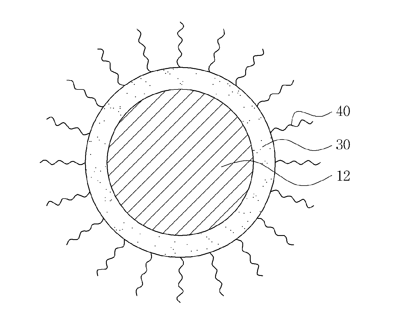
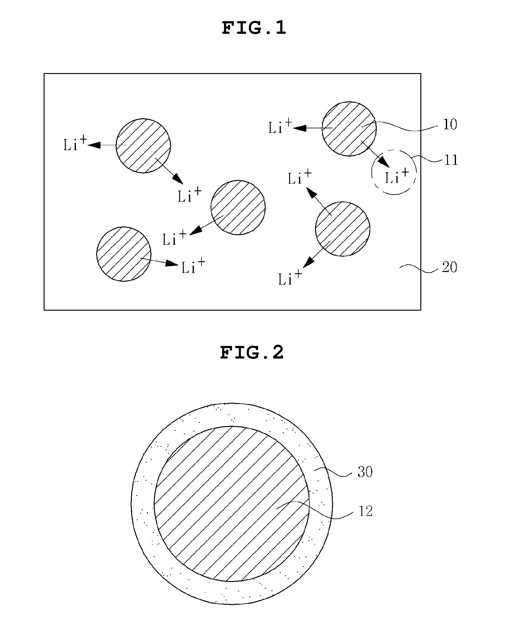
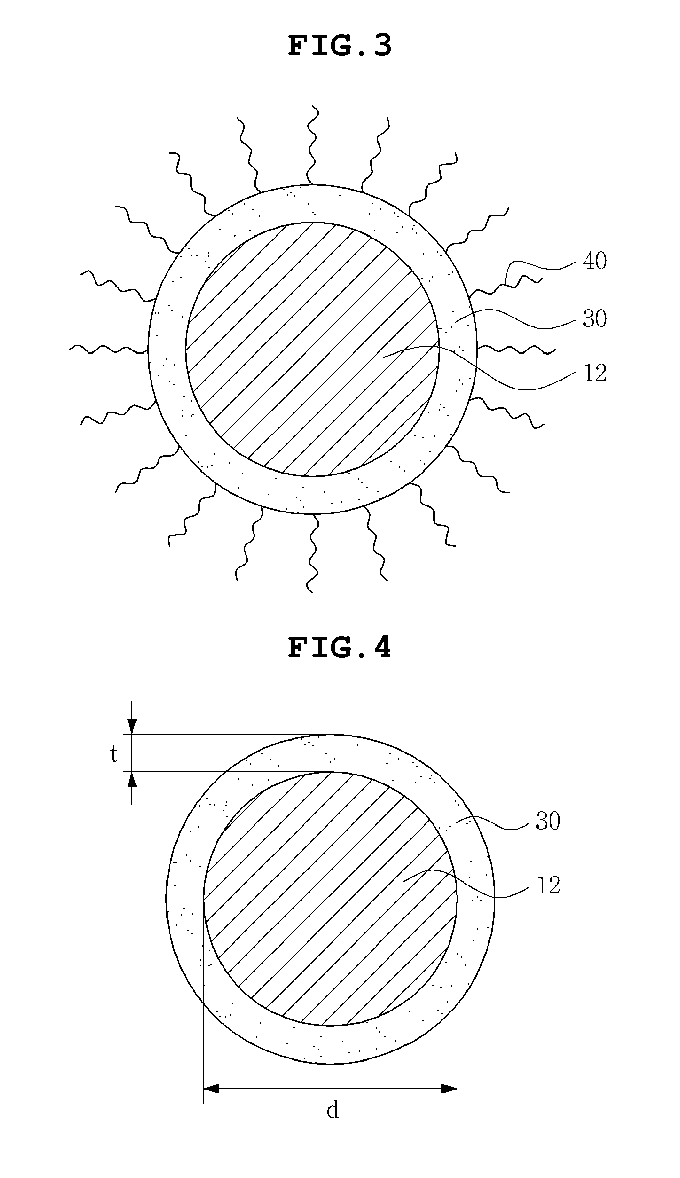
[0010]In embodiments of the present invention, existing problems according to the prior art may be solved by coating a material that decreases diffusion of ions such as lithium

Problems solved by technology

In addition, in order to satisfy the demand in lightness and slimness as described above, a wiring of the printed circuit board is more complicated and has high density.
However, in the case in which the wiring of the printed circuit board is formed in multilayered layers, the insulating layer between the wiring layers should be significantly thin, and therefore, there is a limitation in using the glass fiber having a large volume in the thin insulating layer.
However, when the added content of the filler increases, this causes the insulating resin composition to become brittle, such that processability thereof is deteriorated, and in particular, close adhesion between the insulating layer and a circuit pattern layer multilayered thereon is also deteriorated.
KR 10-2003-0

Method used


Image

  • Inorganic filler, and insulating resin composition, insulating film, prepreg and printed circuit board including the same
  • Inorganic filler, and insulating resin composition, insulating film, prepreg and printed circuit board including the same
  • Inorganic filler, and insulating resin composition, insulating film, prepreg and printed circuit board including the same

Examples


example 1

Preparation of Powder Having β-Eucryptites Dispersed therein, the β-Eucryptite Having Silica Layer Introduced thereinto

[0060]Ethanol (more than 99.5%) of 260 g was added to the dispersion solution of 60 g prepared by Comparative Example 1, thereby preparing a dispersion solution 2 having solid content of 6.25 wt %. Tetraethyl orthosilicate (TEOS) of 4 g and an ammonia solution (NH4OH 25%) of 13 g were added to the dispersion solution 2, followed by stirring at room temperature for 6 hours, to prepare β-eucryptite having a silica layer formed therein. The solution prepared as described above was centrifuged and dried for 5 or more times to prepare a β-eucryptite / silica core-shell powder.

example 2

Preparation of Bismaleimide Resin Solution having 3-Eucryptite Added thereto, the β-Eucryptite Having Silica Layer Introduced thereinto

[0061]Bismaleimide of 20 g was put into dimethylaceteamide (DMAc) of 80 g, followed by stirring for 1 hour, to prepare a bismaleimide resin solution in a content of 20 wt %. The β-eucryptite / silica core-shell of 5 g prepared by Example 1 was added to the above bismaleimide resin solution in a content of 20 wt %, followed by ultra sonication for 2 hours, to prepare a bismaleimide solution having the β-eucryptite / silica core-shell powder contained therein.

example 3

Preparation of Bismaleimide Resin Solution Having β-Eucryptite Added thereto, the β-Eucryptite Having Silica Layer Treated by Vinyltrimethoxy Silane and Introduced thereinto

[0062]Vinyltrimethoxy silane of 0.05 g was added to the β-eucryptite / silica core-shell of 5 g prepared by Example 1, followed by stirring for 2 hours. Then, the prepared solution was added to DMAc of 80 g and bismaleimide of 20 g, followed by ultra sonication, to prepare a bismaleimide solution having the β-eucryptite / silica core-shell powder contained therein.

[0063]A gelation extent of each solvent depending on time was measured by using each each resin composition prepared by Comparative Example 2 and Example 2, and results thereof were shown in the following Table 1. The gelation extent was indirectly measured by comparing an increased extent viscosity with each other.

TABLE 1Comparative Example 2Example 2Day(Viscosity, cps)(Viscosity, cps)14013982521400356040246214055763416684642071,00644581,54045092,406465103...


PUM

PropertyMeasurementUnit
Thicknessaaaaaaaaaa
Thicknessaaaaaaaaaa
Diameteraaaaaaaaaa

Abstract

An inorganic filler has a negative coefficient of thermal expansion, and a shell thereon that decreases diffusion of ions contained in the inorganic filler to outside of the shell and organic filler.

Description

CROSS-REFERENCE TO RELATED APPLICATIONS[0001]This application claims the foreign priority benefit of Korean Patent Application No. 10-2013-0089589, filed on Jul. 29, 2013 in the Korean Intellectual Property Office and entitled “Inorganic Filler, and Insulating Resin Composition, Insulating Film, Prepreg, and Printed Circuit Board Comprising the Same”, the disclosure of which is hereby incorporated by reference in its entirety into this application.BACKGROUND[0002]1. Field[0003]Embodiments of the present invention relate to an inorganic filler, and an insulating resin composition, an insulating film, a prepreg, and a printed circuit board including the same.[0004]2. Description of the Related Art[0005]In order to secure reliability in various electronic devices, various conditions such as electrical insulation, thermal stability, and mechanical stability are demanded in insulating layers of printed circuit boards, and the like, used in the various electronic devices. In particular, a...

Claims


Application Information

Patent Timeline
IPC IPC(8): H05K1/03H05K1/02C09C1/40
CPCH05K1/0373C09C1/405H05K1/0298H05K2201/068C01P2004/61H05K2201/0209C01P2004/64C01P2004/62C01P2004/80C01P2006/22C09C3/063C09C3/12H05K1/036H05K1/0366H05K3/4676H05K2201/0191H05K2201/0195H05K2201/0227H05K2201/0239
Inventor HONG, JIN HOYUN, GEUM HEEJO, DAE HUILEE, SA YONGKIM, JIN YOUNGLEE, KEUN YONG
Owner SAMSUNG ELECTRO MECHANICS CO LTD
Why Eureka
Try Eureka