Dielectric barrier discharge-type electrode structure for generating plasma having conductive body protrusion on electrodes

a technology of conductive body and electrode structure, which is applied in the direction of discharge tube main electrodes, corona discharge, separation processes, etc., can solve the problems of long lifespan, short lifespan of anions, and long lifespan of anions, so as to achieve excellent plasma efficiency, long lifespan, and less noise

Active Publication Date: 2015-05-21
SP TECHNOLOGY CO LTD
View PDF0 Cites 26 Cited by
  • Summary
  • Abstract
  • Description
  • Claims
  • Application Information

AI Technical Summary

Benefits of technology

[0061]The plasma electrode structure of the present invention having the above-described structure generates less noise, has excellent plasma efficiency, generates many active species, has long lifespan, causes less counter-pressure of air, has excellent power consumption, and ensures removal of air conditioner odor as well as air cleaning and sterilization.
[0062]Moreover, it is possible to configure the plasma electrode structure in various manners depending on the characteristics required for each application, which makes it possible to overcome most limitations in electrode design due to the existing plasma e

Problems solved by technology

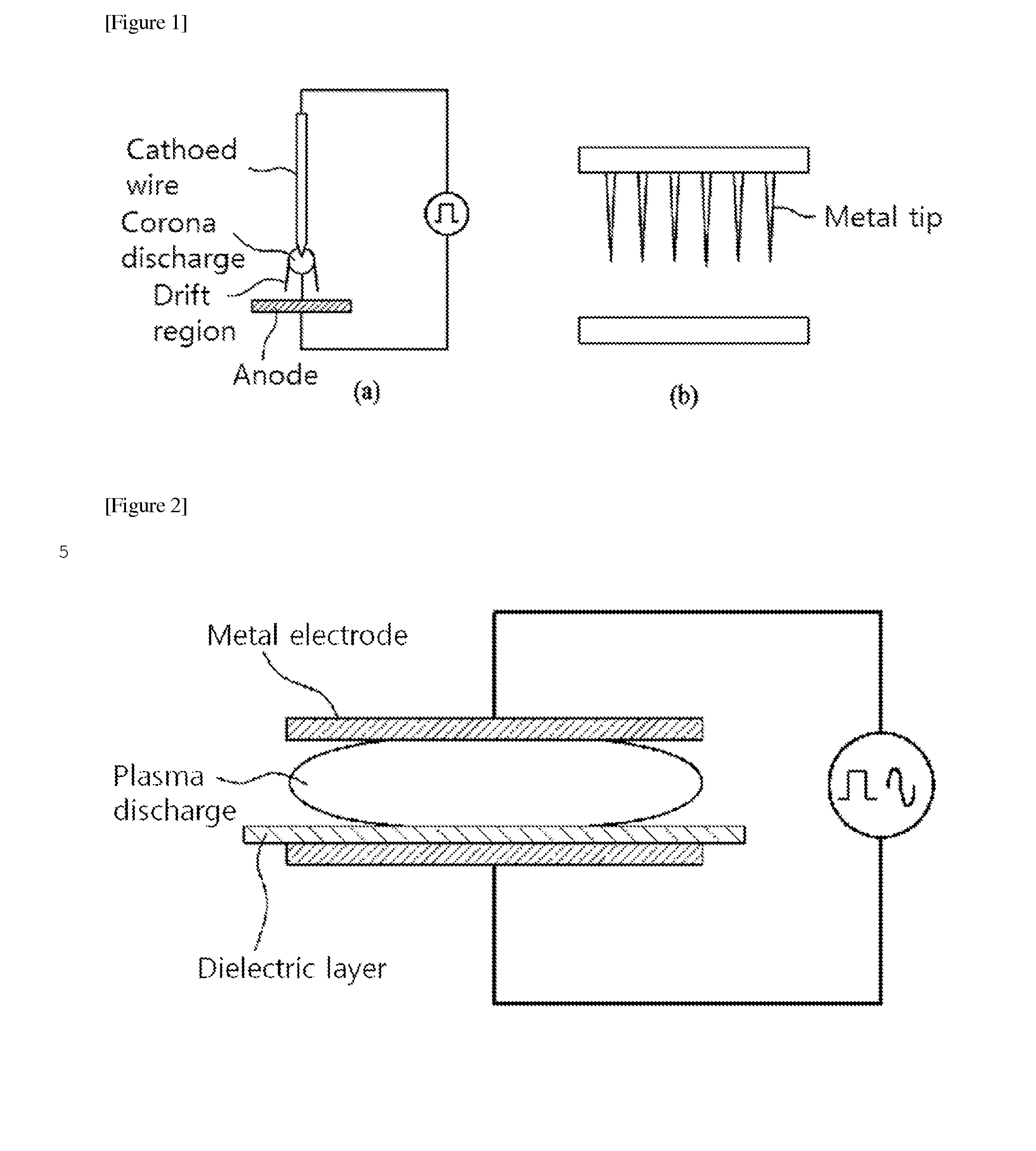
The corona discharge electrode is easy to manufacture and has a simple structure, resulting in low prices.
However, a large amount of ozone is generated during the discharge and its long lifespan does harm to the human body.
Moreover, the generated anions have a very short lifespan, and the amount of ultraviolet rays produced is also small, resulting in a low sterilizing effect.
Furthermore, the plasma volume is very small, and thus the plasma treatment area is limited to a small area.
When an insulator is used, in the case of DC power, the flow of current through the electrode is impossible, and thus an AC power is used to generate the plasma.
According to this structure, the electric field applied to the surface is uniform, and thus charges are non-uniformly accumulated in the dielectric with a specific statistical distribution pattern, which induces a streamer discharge, not the glow discharge, thus reducing the amount of ultraviolet rays produced.
However, this structure tends to generate noise and exerts high counter-pressure against the flow of fluid due to a high discharge voltage and a narrow gap between the electrodes.
Accordingly, as disclosed in Korean Patent Publication No. 10-2002-0046093, it is necessary to extend the electrodes having the same structure in parallel to increase the processing capacity, but the structure is complicated, and the generation of counter-pressure cannot be avoided due to the cross-sectional area of the electrodes.
Moreover, a method of forming a gap between two electrodes used in this publication employs macroscopic units in millimeters (mm) or more by the structural design of the mechanism, which corresponds to the typical method,

Method used


Image

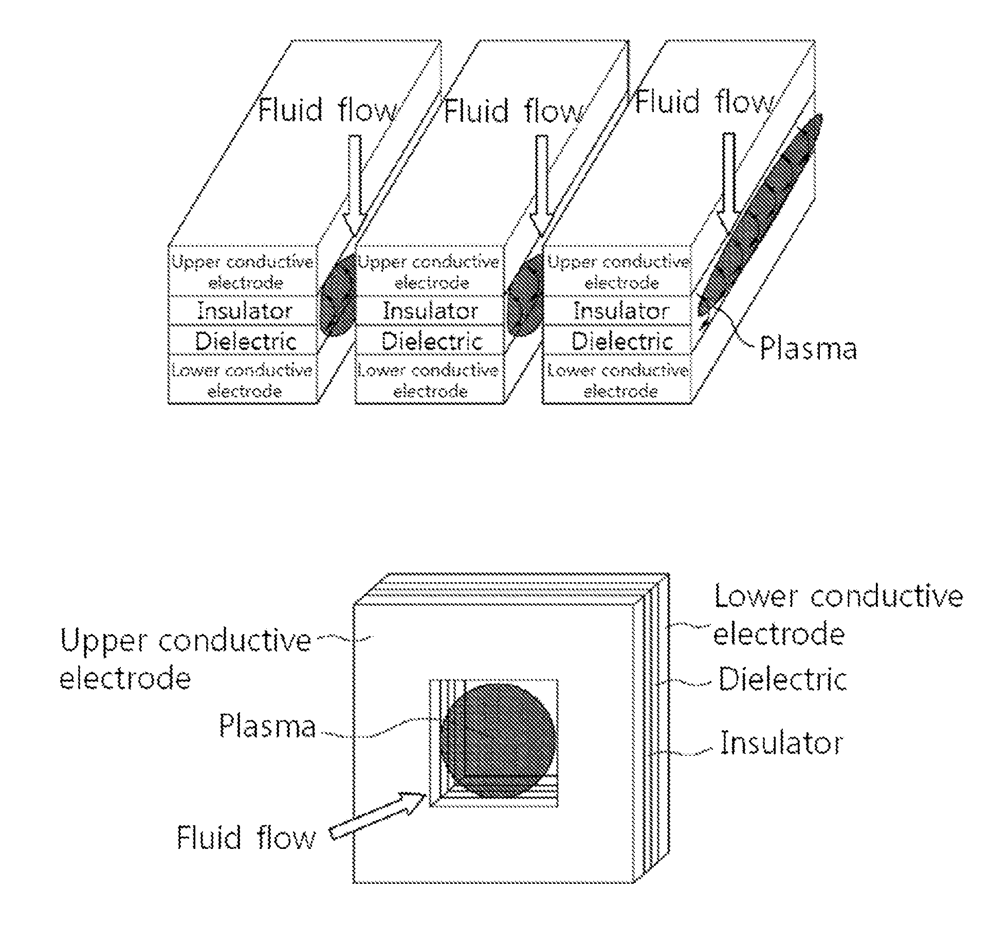
  • Dielectric barrier discharge-type electrode structure for generating plasma having conductive body protrusion on electrodes
  • Dielectric barrier discharge-type electrode structure for generating plasma having conductive body protrusion on electrodes
  • Dielectric barrier discharge-type electrode structure for generating plasma having conductive body protrusion on electrodes

Examples


example 1

[0142]In order to evaluate the performance of a plasma electrode structure, an air cleaning module comprising a fluid inlet, a plasma electrode, and a fluid outlet was used. An electrical electrode was made of stainless steel 403 with a circular plate shape having a diameter of 50 mm and a thickness of 1 mm. Then, five electrode protrusions were formed on the outer periphery of the diameter of the plate at a uniform angle and a height of 50 μm using a press, and five protrusions were formed in the center of the radius in the same manner. Moreover, forty eight circular through holes having a diameter of 3.6 mm were uniformly distributed on the plate. The opening area corresponds to 25% of the whole area. Then, a dielectric layer was formed with a thickness of 70 μm on a circular metal plate by a typical spraying process using alumina and barium titanate powders having a particle size of 1-2 um as a dielectric composition and polyvinylidene fluoride (PVDF) as a binder, and another cir...

example 2

[0145]The electric energy applied to the electrode, i.e., the number of anions generated with an increase in pulse width was measured and shown in FIG. 14. As shown in FIG. 14, it can be seen that the number of anions generated with an increase in pulse width was rapidly increased, and the number of anions was close to 1 million per cubic centimeter as the pulse width was close to 100 μs.


PUM


Abstract

Provided is a dielectric barrier discharge-type electrode structure for generating plasma. The electrode structure, according to the present invention, comprises: an upper conductive body electrode and a lower conductive body electrode; at least one conductive body electrode protrusion portion, which is formed on at least one surface of the upper conductive body electrode and/or the lower conductive body electrode; a dielectric layer which is formed on at least one of the inner surfaces of the upper conductive body electrode and the lower conductive body electrode that face each other, so as to have a substantially uniform thickness; and a specific gap (d) which is formed between the upper and lower conductive body electrodes and the dielectric layer, or between dielectric layers, due to the protruding effect of the conductive body electrode protrusion portion when the upper conductive body electrode and the lower conductive body electrodes come into close contact, wherein the plasma is generated by applying a pulse power or an alternating power to the upper conductive body electrode and the lower conductive body electrode.

Description

TECHNICAL FIELD[0001]The present invention relates to a plasma electrode structure applied to an air cleaning system and the like and, more particularly, to a dielectric barrier discharge (DBD)-type plasma generating electrode structure which generates a plasma in a gaseous fluid such as air such that electrons, ions, ultraviolet rays, etc. generated at this time react with bacteria and odor molecules to exhibit harmful gas decomposition and sterilization, thereby purifying the air present in an air conditioner, a refrigerator, a washing machine, a vehicle, etc.BACKGROUND ART[0002]With the increasing importance of indoor air cleaning, various methods for simultaneously removing particles and gaseous substances present in the room have been developed. These air cleaning techniques include filter type, electrostatic precipitation type, plasma type, UV / photocatalytic type, hybrid type with several methods, etc.[0003]Among others, it is known that the air cleaning method using plasma ha...

Claims


Application Information

Patent Timeline
IPC IPC(8): H01J1/88A61L2/14A61L9/22H05H1/24H01J1/02
CPCH01J1/88H05H1/2406H01J1/02H05H2001/2437A61L2/14H05H2001/2412A61L9/22H01T19/04H01T23/00H05H1/2437B01D53/32H05H1/34
Inventor SOHN, HEE SIK
Owner SP TECHNOLOGY CO LTD
Why Eureka
Try Eureka