
Method For Analyzing Sample Components

a sample component and component technology, applied in the field of sample component analysis, can solve the problems of limiting the use of hcp characterization methods, affecting product quality and safety, and being labor-intensive and cumbersom

Active Publication Date: 2015-06-11
UNIV OF NOTRE DAME DU LAC +1
View PDF0 Cites 20 Cited by
  • Summary
  • Abstract
  • Description
  • Claims
  • Application Information

AI Technical Summary

Benefits of technology

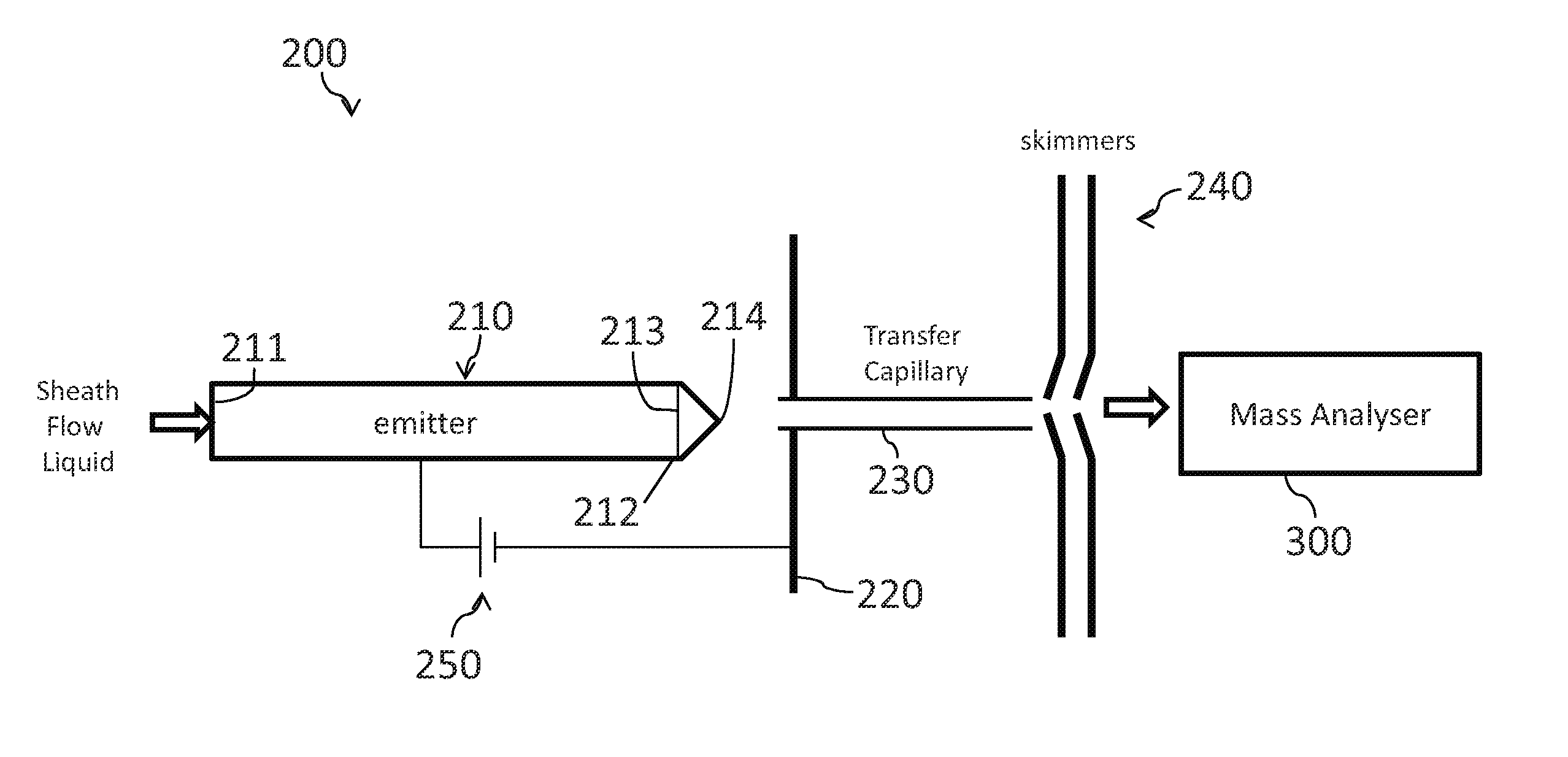
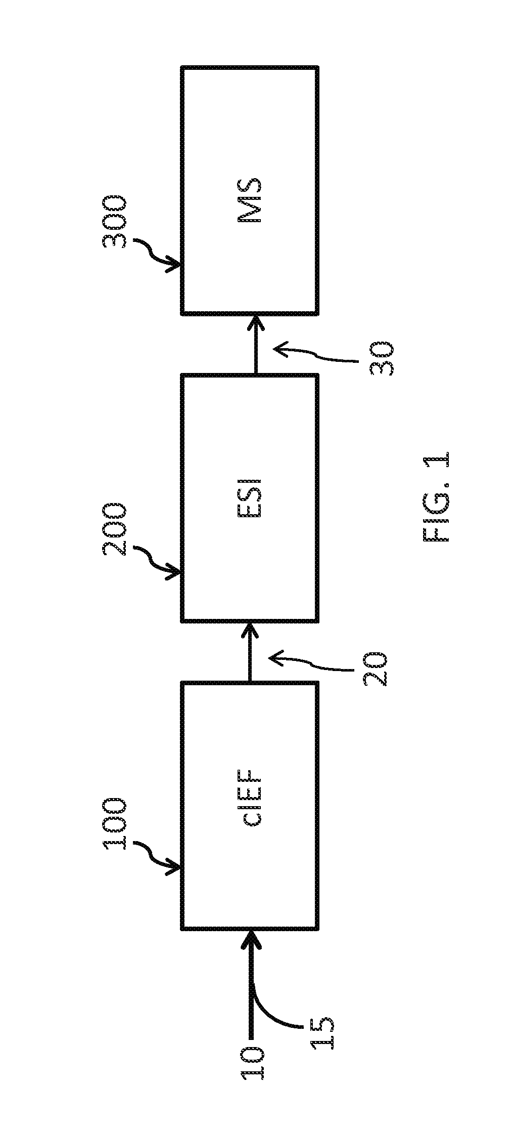
The patent describes a method for identifying and analyzing components in a sample, particularly in a sample that includes a heterogeneous mixture of biomolecules. The method involves separating the components in the sample using a capillary isoelectric focusing (cIEF) process and then transferring them to an ionization instrument for analysis using mass spectrometry (MS). The method also includes using a sheath flow solution for both separating and ionizing the sample components. The technical effects of this patent include improved accuracy and sensitivity in identifying and analyzing sample components, as well as improved efficiency and accuracy in mass spectrometry analysis.

Problems solved by technology

HCP can potentially impact product quality and safety.
Current characterization methods for HCP, such as two-dimensional gel electrophoresis, tend to be labor-intensive and cumbersome, which can limit the use of these methods for HCP characterization, particularly during commercial production.
However, on-line coupling of cIEF with ESI-MS for biological samples, especially protein digests, has been challenging.

Method used


Image

  • Method For Analyzing Sample Components
  • Method For Analyzing Sample Components
  • Method For Analyzing Sample Components

Examples


working examples

[0108]All reagents were purchased from Sigma Aldrich Co. (St. Louis, Mo., USA) unless otherwise stated.

example 1

Sample Preparation

Preparation of BSA Digest

[0109]A Bovine Serum Albumin (BSA) digest (0.1 mg / mL) was used to evaluate the reproducibility of the cIEF-ESI-MS / MS system. BSA (0.5 mg / mL) was dissolved in 100 mM ammonium bicarbonate (pH 8.0) and denatured at 90° C. for 10 minutes, followed by standard reduction and alkylation process by reduction with dithiothreitol (DTT) (8 mM) at 65° C. for 1 h and alkylation with iodoacetic acid (IAA) (20 mM) at room temperature for 30 min in the dark. Digestion was performed by incubating the proteins for 12 hours at 37° C. with trypsin at a trypsin:protein ratio of 1:30 (w / w). Carboxyl functionalized magnetic microspheres (BioMag®Plus carboxyl, mean diameter ˜1.5 μm) were purchased from Bangs Laboratories, Inc. (Fishers, 1N, USA) and activation of carboxyl functionalized magnetic microspheres and trypsin immobilization was performed as described by Li et al., J. Chromatogr. A 2011, 1218, 2007-2011.

Preparation of a Three Protein Mixture

[0110]A three...

example 2

cIEF

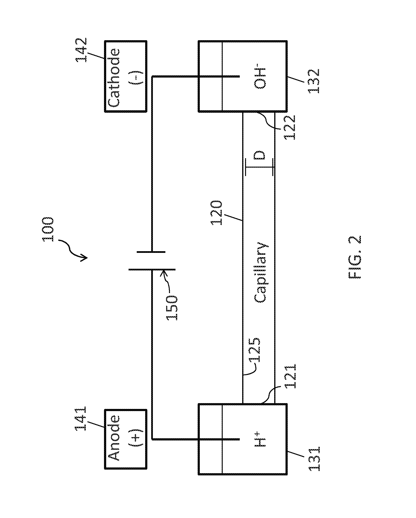
[0113]The instrument used in this example was based on a capillary electrophoresis system described by Wojcik et al., Rapid Commun. Mass Spectrom. 2010, 24, 2554-2560. A commercial linear polyacrylamide (LPA) coated capillary (50 μm i.d., 150 μm o.d., 50 cm long, Polymicro Technologies, Phoenix, Ariz.) was used for the cIEF separation. The anode end of the capillary was placed in formic acid (0.1%, pH 2.5), and the cathode end was placed in 0.3% ammonium hydroxide (pH 11). The capillary was filled with sample prepared in a 0.4% Pharmalyte (3-10) solution (GE Healthcare, Piscataway, N.J.) by purging the solution through the capillary at 2 psi for 3 minutes. The injection volume employed in this experiment is equal to the capillary volume. Focusing voltage was applied at 360 V / cm for 10 minutes.


PUM

PropertyMeasurementUnit
focusing voltageaaaaaaaaaa
pKaaaaaaaaaaa
pKaaaaaaaaaaa

Abstract

Described herein is a method and system for on-line coupling of capillary isoelectric focusing (cIEF) to high-resolution mass spectrometry in which a sheath flow buffer comprising polar organic solvent and organic acid is used as both an immobilization solution for (cIEF) and an ionization solution for electrospray ionization (ESI).

Description

BACKGROUND OF THE INVENTION[0001]Recombinant proteins are becoming increasingly important as therapeutics. Recombinant proteins can be manufactured using cell lines, for example non-human mammalian host cell lines, which are engineered to express certain human gene sequences to produce a protein of interest. After the target protein is produced in the cell culture, it can be purified through known processes to high levels of purity. However, trace amounts of contaminant proteins produced by the host cell line (called Host Cell Proteins, or HCP) can be present in the depleted cell culture.[0002]HCP can potentially impact product quality and safety. Consequently, it is important to characterize HCP present in therapeutic products to mitigate these risks. Current characterization methods for HCP, such as two-dimensional gel electrophoresis, tend to be labor-intensive and cumbersome, which can limit the use of these methods for HCP characterization, particularly during commercial produc...

Claims


Application Information

Patent Timeline
Patent Type & Authority Applications(United States)
IPC IPC(8): H01J49/00H01J49/16G01N27/447H01J49/26
CPCH01J49/0031G01N27/447H01J49/165H01J49/26G01N27/4473G01N27/44795
Inventor MCGIVNEY, JAMESZHU, GUIJIEDOVICHI, NORMAN
Owner UNIV OF NOTRE DAME DU LAC
Learn More