
Composite porous separation membrane having shut-down function, method of manufacturing same, and secondary batteries using same

a technology of porous separation membrane and composite porous membrane, which is applied in the direction of battery, sustainable manufacturing/processing, cell components, etc., can solve the problems of battery circuit, deterioration of safety, and lowering of battery performan

Active Publication Date: 2015-06-11
AMOGREENTECH CO LTD
View PDF0 Cites 35 Cited by
  • Summary
  • Abstract
  • Description
  • Claims
  • Application Information

AI Technical Summary

Benefits of technology

The present invention is about a new composite porous separator and a secondary battery using it. The new separator has a porosity that is the same as or similar to a porous polymer web layer laminated on a porous substrate, which prevents the porosity of the separator from being dependent on the substrate. This allows the high-porosity properties of the polymer web layer to improve ionic mobility. The new separator also includes a first porous polymer web layer as an adhesive layer and a heat-resistant second porous polymer web layer on one side of a porous substrate, which improves the adhesion between the separator and the electrode, prevents degradation of battery performance, and enhances safety. Additionally, the new separator has a shutdown function and utilizes the properties of a porous substrate with a lower melting point to secure safety. Furthermore, the new separator is cost-effective as it uses a porous substrate as a strength support. This invention solves the problems of conventional art and provides a new generation of composite separators with improved properties for secondary batteries.

Problems solved by technology

Accordingly, the lithium ion delivery is not effectively achieved through pores of the separator, and thus the battery performance is lowered.
Further, the conventional separator is made of a chemically stable material that does not cause decomposition and reaction when being exposed to an oxidizing and reducing atmosphere inside the battery, for example, a fluorine-based polymer, in which the mechanical strengths of these substrates are not satisfactory, to thus cause problems such as peeling and breakage of the separator during an assembly process of the battery, and to thereby cause deterioration of safety such as internal short-circuit of the battery.
However, the inorganic particles are desorbed due to a low binding capability between the separator and the inorganic particles, to thus fail to realize a desired effect.
When the separator is melted as the temperature gets higher, a big hole is created to thus cause a short circuit to occur between the anode and the cathode.
It is very deficient to use an existing lithium-ion secondary battery using a polyolefin separator and a liquid electrolyte or an existing lithium-ion polymer battery using a polymer electrolyte that is obtained by coating a gel polymer on a gel polymer electrolyte or a polyolefin separator, for a high-energy density and large-capacity secondary battery in terms of the heat-resistance.
Therefore, the heat-resistance performance that is required for a high-capacity and large-area secondary battery for automobiles does not meet the safety requirements.
In the Korean Patent Application Publication No. 2008-13209, since a conventional polyolefin-based porous film used as a separator is used as a central substrate, the fibrous layer laminated on the polyolefin-based porous film having a low porosity may have a limitation that any layer of a multilayer structure cannot have excellent properties of a porous web obtained by an electrospinning method, particularly, ion conductivity due to a high porosity.

Method used


Image

  • Composite porous separation membrane having shut-down function, method of manufacturing same, and secondary batteries using same
  • Composite porous separation membrane having shut-down function, method of manufacturing same, and secondary batteries using same
  • Composite porous separation membrane having shut-down function, method of manufacturing same, and secondary batteries using same

Examples


first embodiment

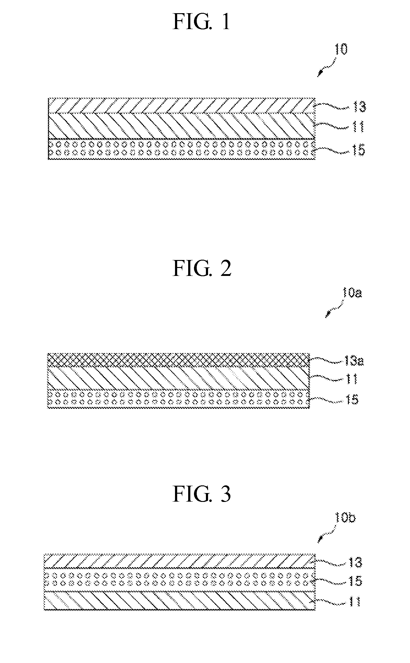
[0042]First, as shown in FIG. 1, a composite porous separator 10 according to the present invention has a shutdown function, and includes a first porous polymer web layer 13 acting as an adhesive layer and a second porous polymer web layer 15 containing an electrolytic solution as a heat-resistant support on both sides of a porous substrate 11 used as a support, respectively.

[0043]The porous substrate 11 is set to have a melting point relatively lower than the first porous polymer web layer 13 and the heat-resistant second porous polymer web layer 15 laminated on both sides of the porous substrate 11, to thereby make the separator have a shutdown function when the temperature rise is achieved.

[0044]For this purpose, the porous substrate 11 may employ a porous membrane made of polyethylene (PE) whose melting point is about 120° C., or a nonwoven fabric made of a PP / PE or PET fiber, in consideration of safety of a secondary battery in which boiling of an electrolytic solution occurs a...

second embodiment

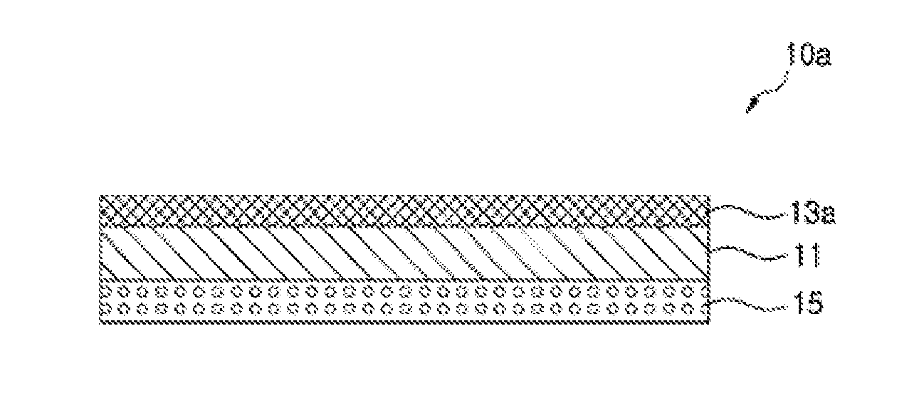
[0050]Further, in the case that the porous substrate 11 is made of a nonwoven fabric formed of PP / PE or PET fibers, the nonwoven fabric has too large pores and thus the first porous polymer web layer 13 is transformed into a non-pore polymer film layer 13a to preferably use the thin-film non-pore polymer film layer 13a in place of the first porous polymer web layer 13 to lower the porosity of the porous substrate 11 on one side of the porous substrate 11, like the separator 10a of the second embodiment shown in FIG. 2.

[0051]The first porous polymer web layer 13 and the non-pore polymer film layer 13a are swelled in the electrolyte solution, and may be made of any one of a polymer capable of conducting the electrolytic ions, for example, PVDF (polyvinylidene fluoride), PEO (polyethylene oxide), PMMA (polymethyl methacrylate), TPU (thermoplastic polyurethane). In this case, the PVDF is the most preferable polymer having a swelling property in the electrolyte solution, enabling the ele...

third embodiment

[0071]That is, the composite porous separator 10b according to the present invention is configured by sequentially laminating the mineral-containing second porous polymer web layer 15 and the first porous polymer web layer 13 on any one side of the porous substrate 11 in the case that the porous substrate 11 is made of a PE porous membrane.

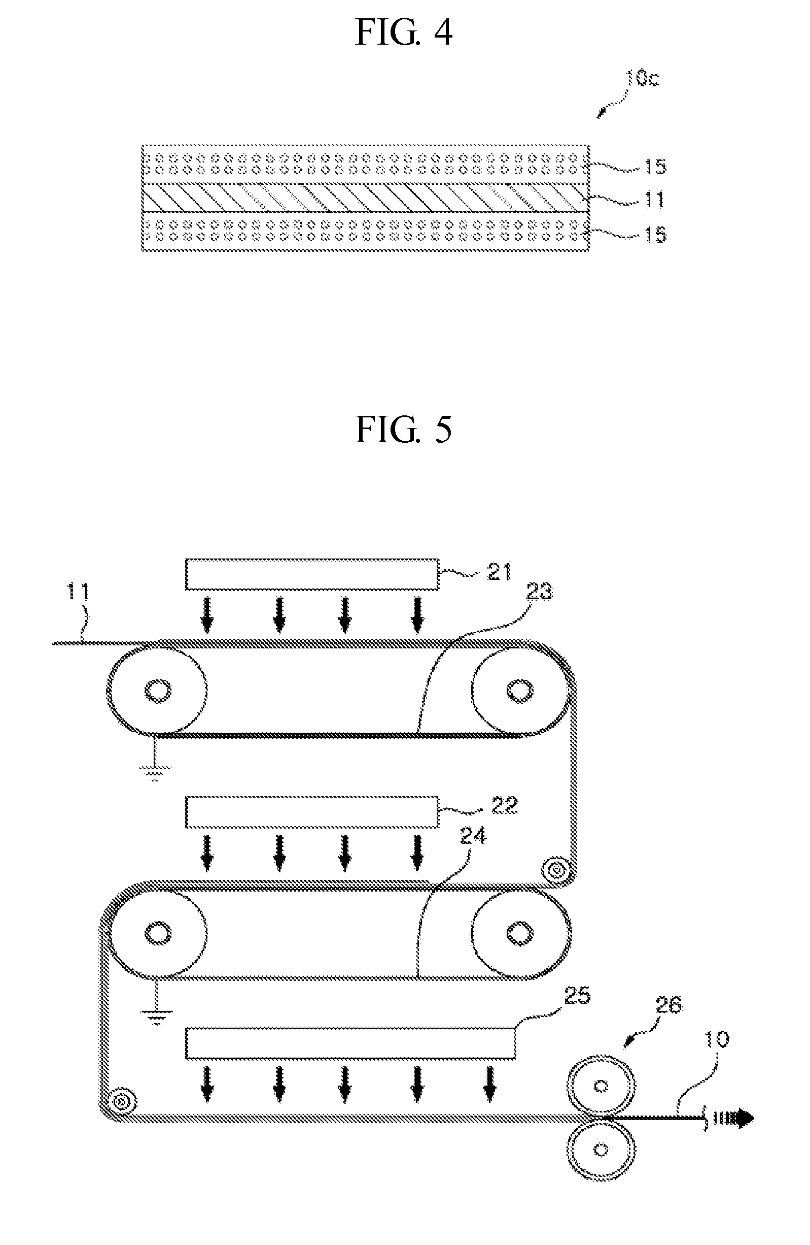
[0072]The laminated structure of the second porous polymer web layer 15 containing inorganic materials and the first porous polymer web layer 13 is configured by the following processes of: preparing a multi-hole nozzle pack in which a plurality of first spinning nozzles and a plurality of second spinning nozzles are disposed along the traveling direction of a collector; spinning a second spinning solution from the second spinning nozzles on the upper surface of the porous substrate 11, to thus form the mineral-containing second porous polymer web layer 15; spinning a first spinning solution from the first spinning nozzles on the upper surface of ...


PUM

PropertyMeasurementUnit
porositiesaaaaaaaaaa
sizeaaaaaaaaaa

Abstract

A composite porous separator includes: a porous substrate acting as a support and having a first melting point and a first porosity; a first porous polymer web layer that is laminated on one side of the porous substrate, and acts as an adhesive layer when being in close contact with an opposing electrode; and a second porous polymer web layer that is laminated on the other surface of the porous substrate, and is formed of nanofibers of a heat-resistant polymer, in which the first porous polymer web layer and the second porous polymer web layer have a melting point higher than the first melting point of the porous substrate and a porosity that is the same as or similar to the first porosity of the porous substrate, respectively.

Description

CROSS REFERENCE TO RELATED APPLICATIONS[0001]This application is a divisional of International Application No. PCT / KR2013 / 007442, filed on Aug. 20, 2013, which claims priority to and the benefit of Korean Application No. 10-2012-0091332, filed on Aug. 21, 2012, in the Korean Patent Office, the entire contents of which are incorporated herein by reference.TECHNICAL FIELD[0002]The present invention relates to a composite porous separation membrane (hereinafter, referred to as a separator) having a shut-down function, a method of manufacturing same, and a secondary battery using same. More particularly, the present invention relates to a composite porous separator having a shut-down function, which can improve ion mobility properties of the separator and has a shut-down function by a porous substrate, a method of manufacturing same, and a secondary battery using same.BACKGROUND ART[0003]A lithium secondary battery is generally assembled with and includes an anode as a negative electrod...

Claims


Application Information

Patent Timeline
Patent Type & Authority Applications(United States)
IPC IPC(8): H01M2/16H01M2/14H01M10/42H01M50/403H01M50/417H01M50/431H01M50/443H01M50/451H01M50/454H01M50/457H01M50/489H01M50/491H01M50/494
CPCH01M2/1686H01M2/1606H01M2/145H01M10/4235H01M2/1646H01M10/052H01M50/44H01M50/431H01M50/489H01M50/417H01M50/494H01M50/451H01M50/491H01M50/443H01M50/457H01M50/403H01M50/454H01M2220/20Y02E60/10H01M50/446H01M10/05H01M50/449H01M50/572H01M50/414Y02P70/50Y02T10/70
Inventor LEE, SEUNG HOONJUNG, YONG SIKSO, YUN MI
Owner AMOGREENTECH CO LTD
Learn More