Notably, for tests such as mammograms, variations in
biological tissue may result in only a subtle x-ray absorption
image contrast, making unambiguous detection of tumors or anomalous tissue difficult.
However, for the prior art configurations described so far, x-ray power is a problem.
However,
electron bombardment of the target also causes heating, and the x-ray power that can be achieved is limited by the maximum total
electron power that can fall on the microspot without melting the x-ray generating material.
A limited
electron power means a limited x-ray power, and the low x-ray flux achievable with typical x-ray targets may lead to unacceptable long
exposure times when used, for example, for
mammography or other diagnostic tests involving live patients or animals.
The total x-ray flux can be increased by distributing higher electron
power over a larger area, but then the source becomes less coherent, degrading the
image contrast.
Coherent x-rays of higher brightness and sufficient flux can be achieved by using a
synchrotron or free-electron
laser x-ray source, but these machines may occupy facilities that cover acres of land, and are impractical for use in clinical environments.
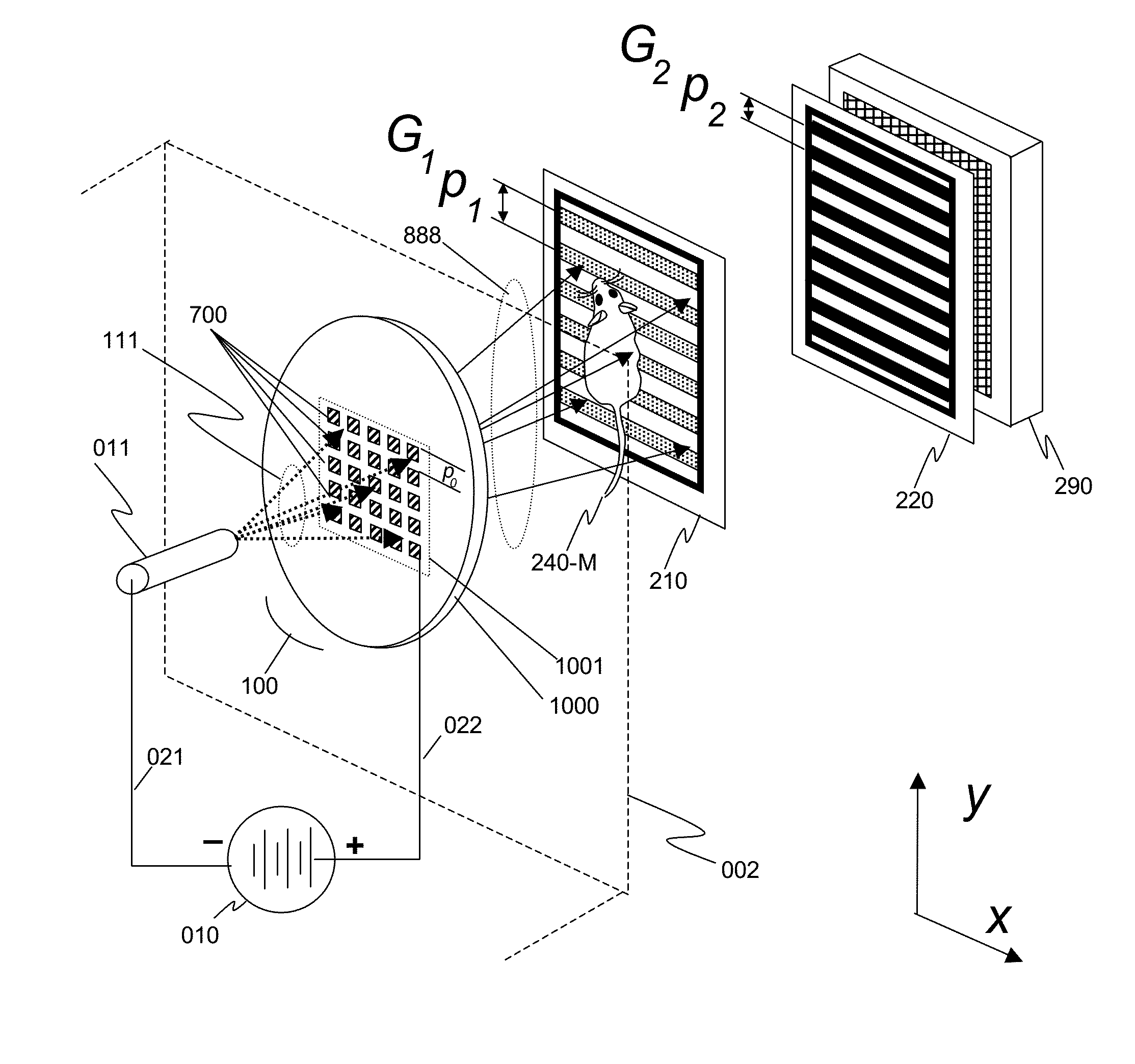
Unfortunately, the current art of Talbot-Lau GBIs have many constraints for most practical applications such as
clinical imaging, including a requirement that both the source grating G0 and the analyzer grating G2 have fine pitches and apertures with large aspect ratios.
In this case, about 75% of the x-rays from the source are blocked due to area shadowing alone, and when gratings with large aspect ratios are used, greater losses occur due to angular shadowing.
As a result, both the G0 and G2 gratings must have small apertures and be of thickness sufficient to minimize unwanted x-ray transmission, which limits the efficient use of the x-rays from the source.
Furthermore, the loss from the analyzer grating G2 further results in a significantly higher
dose (relative to the same system without a G2 grating) for the object under investigation to produce an image with good characteristics due to multiple exposures for phase-stepping and absorption of x-rays resulting in lower
signal-to-
noise.
Smaller apertures can increase the possible
image contrast and resolution by improving
spatial coherence, but decreases the overall number of x-rays in the system, thus requiring longer
exposure times. Moreover, with smaller apertures, these fine gratings become more difficult to manufacture.
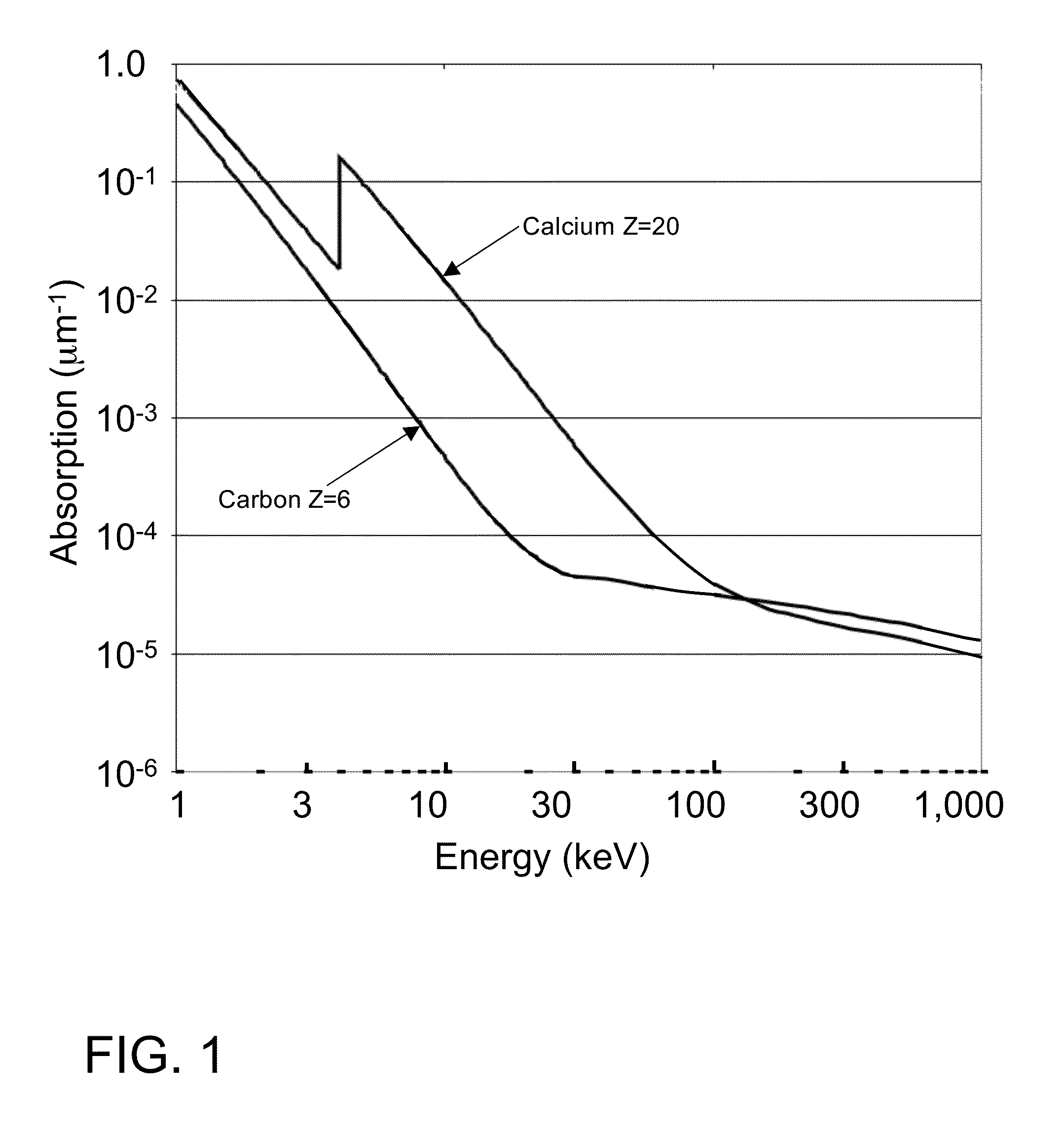
Furthermore, building absorbing gratings such as G0 and G2 for these higher energy, shorter
wavelength x-rays can present difficulties, as the thickness of the gratings must increase exponentially to maintain the same
absorption factor for higher energy x-rays (the x-ray attenuation length is approximately proportional to Ekev3).
The preceding problems of Talbot-Lau GBIs using linear gratings, which can be used for collecting interference data in one dimension only, become more severe if one wishes to generate phase-contrast images in two orthogonal directions.
In addition to challenges associated with the imaging and registration processes, this approach may not be practical, especially when used with living subjects who may move or simply become impatient, and who will incur increased dosage (doubled) if the phase stepping must be performed in two directions.

