
Scr catalysts having improved low temperature performance, and methods of making and using the same

Active Publication Date: 2015-09-03
JOHNSON MATTHEY PLC
View PDF3 Cites 14 Cited by
  • Summary
  • Abstract
  • Description
  • Claims
  • Application Information

AI Technical Summary

Benefits of technology

The present invention describes a method for improving the performance of iron-containing molecular sieves, such as zeolites or SAPOs, in low-temperature environments. By treating the molecular sieve at a high temperature in a non-oxidizing atmosphere with steam, the inventors have discovered that the dispersion of iron to the in ion-exchange sites of the molecular sieve is improved. This improves the low-temperature performance of the iron-containing molecular sieve. Additionally, the invention also provides improved NOx conversion in exhaust gases by contacting it with a molecular sieve that had been treated at a high temperature. This can increase NOx conversion over a wider temperature range than traditional catalysts.

Problems solved by technology

Vanadium-based SCR catalysts are unsuited for higher temperature environments due to their thermal instability.

Method used


Image

  • Scr catalysts having improved low temperature performance, and methods of making and using the same
  • Scr catalysts having improved low temperature performance, and methods of making and using the same
  • Scr catalysts having improved low temperature performance, and methods of making and using the same

Examples


example 1

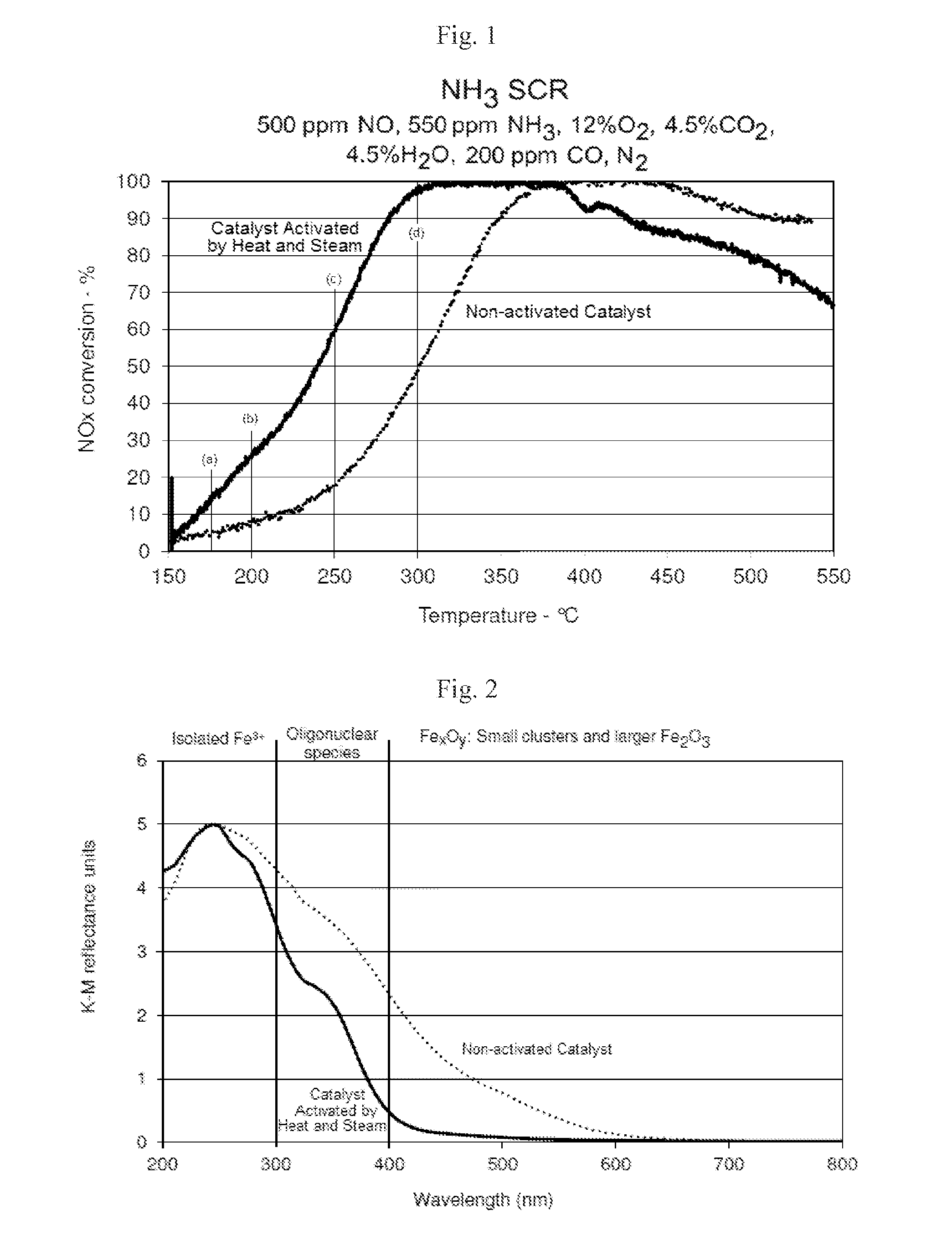
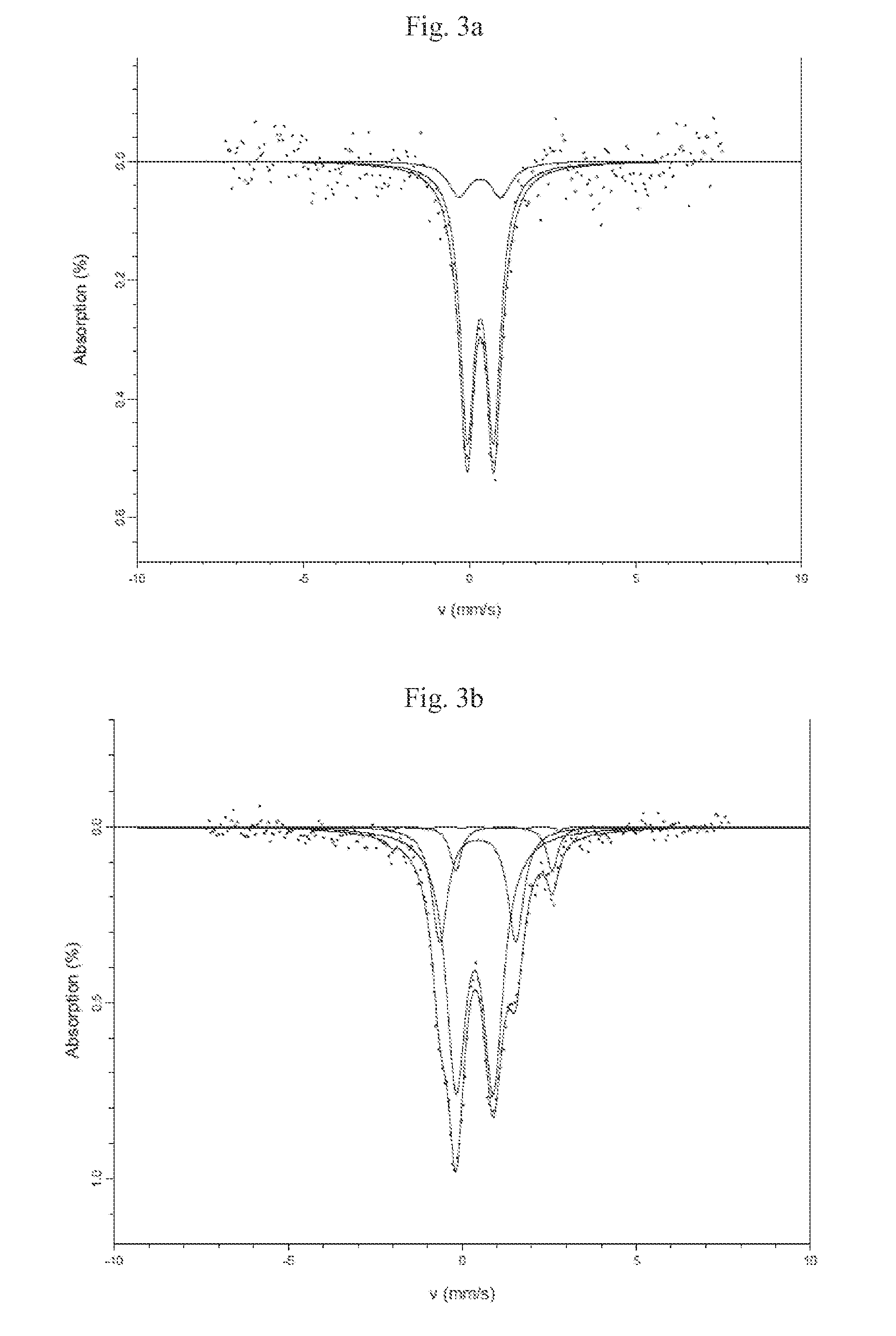
[0048]3 wt % iron was added to a commercially available ferrierite zeolite by spray drying the ferrierite zeolite with ammonium Fe (III) oxalate in solution so as to give the desired Fe loading. One portion of the resulting iron-containing ferrierite was dried at 105° C. overnight and was activated under a flow of10% steam in nitrogen at 800° C. for 1 hour. This material was not subjected to calcination. Another portion of the iron-containing ferrierite was calcined at 500° C. in air for 2 hours to use as reference.

[0049]In the examples that follow, powder samples of the catalysts were obtained by pelletizing the original samples, crushing the pellets and then passing the powder obtained through a 255 and 350 micron sieves to obtain a powder having particle size between 255 and 350 microns. The powder samples were loaded into a Synthetic Catalyst Activity Test (SCAT) reactor and tested using the following synthetic diesel exhaust gas mixture (at inlet) including nitrogenous reductan...

example 2

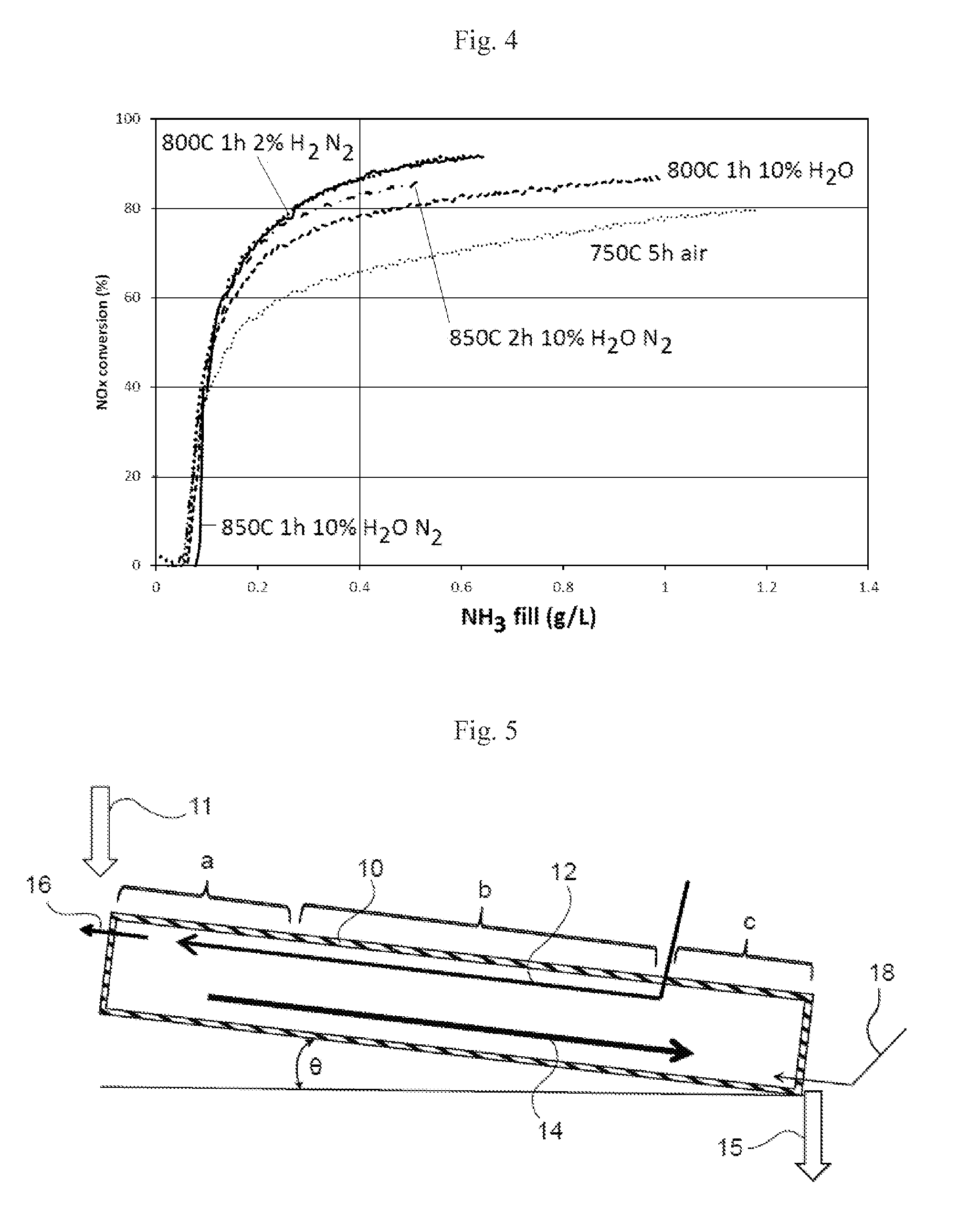
[0056]An iron ferrierite was made as described above by combining 3 wt % iron with a commercially available ferrierite zeolite by spray drying the ferrierite zeolite with ammonium Fe (II) sulphate in solution so as to give the desired Fe loading. A series of powder samples were then prepared by treating the iron ferrierite at the temperatures and atmospheric conditions as shown in Table 1. Samples were prepared for determining their catalytic activity by coating the powder onto ceramic cores.

TABLE 1Conditions for Preparing Modified Iron ZeoliteTemperature (° C.)TimeAtmosphereTreatment8001 h2% H2 + N2Thermal8001 h10% H2O + N2Hydrothermal8501 h10% H2O + N2Hydrothermal8502 h10% H2O + N2Hydrothermal7505 hAirCalcination (Reference)

[0057]The reference sample was prepared by calcination at 750° C. because the ferrierite zeolite was treated with ammonium Fe (II) sulphate and a higher temperature was needed to remove the sulfate.

[0058]The test conditions for the data shown in FIG. 4 were NOx...


PUM

PropertyMeasurementUnit
Temperatureaaaaaaaaaa

Abstract

SCR-active molecular-sieve based catalysts with improved low-temperature performance are made by heating a molecular-sieve in a non-oxidizing atmosphere with steam (hydrothermal treatment), or in a reducing atmosphere without steam (thermal treatment), at a temperature in the range of 600-900° C. for a time period from 5 minutes to two hours. The resulting SCR-active iron-containing molecular sieves exhibit a selective catalytic reduction of nitrogen oxides with NH3 or urea at 250° C. that is at least 50% greater than if the iron-containing molecular-sieve were calcined at 500° C. for two hours without performing the hydrothermal or thermal treatment.

Description

BACKGROUND OF THE INVENTION[0001]1. Field of the Invention[0002]The invention relates generally to molecular sieve based-catalysts used in selectively converting nitrogen oxides (NOx) present in a gas stream to nitrogen using a nitrogenous reductant such as ammonia (NH3) and in particular it relates to Fe-containing catalysts which are particularly active at relatively low temperatures in relation to conventional Fe zeolite catalysts. The molecular sieve in these catalysts is preferably a zeolite or a silicoaluminophosphate (SAPO).[0003]2. Description of Related Art[0004]Selective catalytic reduction (SCR) systems utilize NH3 as a reductant to reduce NOx to elemental nitrogen. A principal application of SCR technology is in the treatment of Nx emissions from internal combustion engines of motor vehicles, and especially lean-bum internal combustion engines. SCR systems are also applied to static sources of NOx, such as power plants.[0005]One class of SCR catalysts is transition metal...

Claims


Application Information

Patent Timeline
IPC IPC(8): B01J29/072B01J29/68C01B39/44C01B39/02C01B39/54B01J29/85B01J29/46
CPCB01J29/072B01J29/85B01J29/68B01J29/46B01J2229/186C01B39/54C01B39/44B01J2229/40B01J2229/36C01B39/02B01D53/9418B01J29/76B01J29/7615B01J29/763B01D2255/20738B01D2255/50B01D2251/2062B01D2251/2067B01D2258/012B01D2258/0283B01J37/0045Y02A50/20Y02T10/12B01D53/94B01J37/02B01J37/10B01J37/14B01J37/16B01J37/18B01J37/08B01J2229/10B01J37/12B01D53/565B01D2255/504B01D53/56B01J37/0036B01D2255/502
Inventor CHANDLER, GUY RICHARDCOLLIER, JILLIAN ELAINEGREEN, ALEXANDER NICHOLAS MICHAELDURAN-MARTIN, DESIREEPHILLIPS, PAUL RICHARDRAJARAM, RAJ RAOREID, STUART DAVID
Owner JOHNSON MATTHEY PLC
Learn More