Fuel cell and method for operating the fuel cell

Active Publication Date: 2015-09-17
SUMITOMO ELECTRIC IND LTD
View PDF0 Cites 9 Cited by
  • Summary
  • Abstract
  • Description
  • Claims
  • Application Information

AI Technical Summary

Benefits of technology

[0035]The present invention can provide a fuel cell that employs a fuel-electrode collector having sufficiently high performance in terms of three items of pressure drop, electric conduc

Problems solved by technology

On the other hand, in order to cause an electrochemical reaction to proceed in a fuel cell at a reaction rate on the practical level, temperatures slightly higher than room temperature are not sufficient for the MEA, the fuel gas, and the like and heating with a heating device needs to be performed.
In order to reduce the time for which protons H+

Method used


Image

  • Fuel cell and method for operating the fuel cell
  • Fuel cell and method for operating the fuel cell
  • Fuel cell and method for operating the fuel cell

Examples


example 1

Influence of Heating Temperature

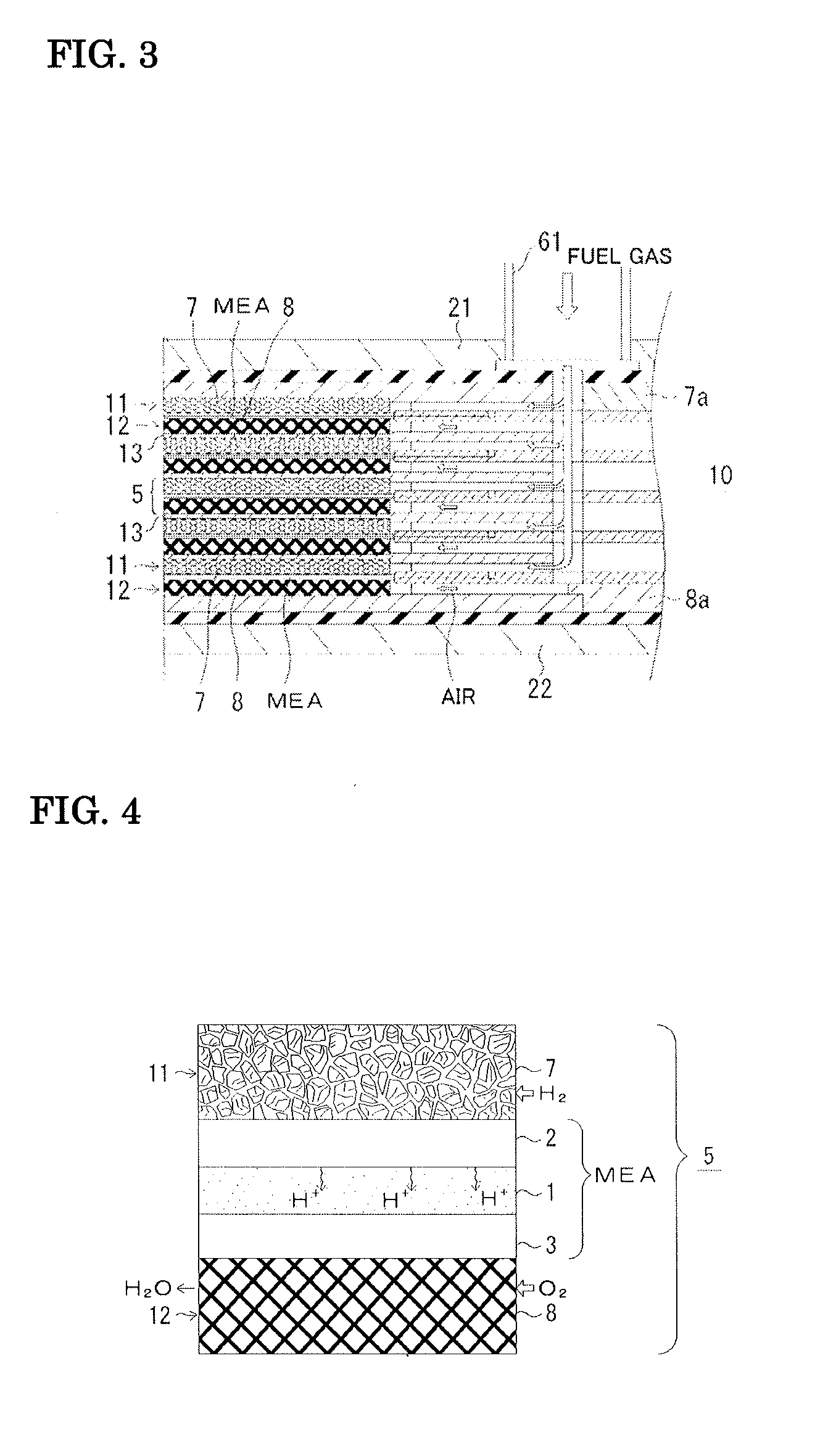
[0073]An anode-support MEA was produced and evaluated in terms of performance. NiO and BCY (barium cerium oxide doped with yttrium) were subjected to ball milling and then to uniaxial molding processing so as to be formed into a sheet. This would serve as a fuel electrode (anode), that is, a Ni-containing BCY anode 2. This anode was preliminarily sintered at 1000° C. Subsequently, BCY paste that would form the solid electrolyte 1 was applied to the preliminarily sintered anode by screen printing. A binder added during the screen printing was evaporated by a binder-removal treatment at 750° C. Co-sintering was performed at 1400° C. After that, lanthanum strontium manganite (LSM) that would form the air electrode (cathode) 3 was applied to the co-sinter and fired at 1000° C. The fuel electrode 2 was equipped with the aluminum-plating porous body 7. The air electrode 3 was equipped with an FeCr alloy wire mesh or a Pt wire mesh. Thus, a cell 5 was provid...

example 2

[0077]An electrolyte-support MEA was produced and evaluated in terms of, for example, influence of humidification. A powder of BZY (barium zirconium oxide doped with yttrium) was subjected to ball milling, then preliminarily fired at 1000° C., and subsequently pulverized by ball milling again. After that, the powder was subjected to uniaxial molding processing and heat-treated in an oxygen atmosphere at 1600° C. for 24 h. Thus, the solid electrolyte 1 was provided. Lanthanum strontium cobalt ferrite (LSCF) that would form the air electrode was applied to the solid electrolyte 1 and fired at 1000° C. The fuel electrode 2 was provided by forming a film of silver (Ag) by electroless plating. Thus, the MEA was produced. After that, as in Example, electrode collectors were disposed. The cell 5 had the following configuration. (air-electrode collector 8 (Fe—Cr alloy or Pt mesh or Ag mesh) / air electrode 3 (LSCF) / solid electrolyte 1 (BZY) / fuel electrode 2 (Ag or Ni-BZY, NiFe-based alloy) / fu...


PUM


Abstract

Provided are a fuel cell that employs a fuel-electrode collector excellent in terms of thermal conductivity and the like, so that it is excellent in terms of power generation efficiency and cost effectiveness; and a method for operating the fuel cell. Included are a membrane electrode assembly (MEA), a fuel-electrode collector that is a porous metal body disposed in contact with a fuel electrode and performing current collection,and a heating device operated by electric power, wherein a solid electrolyte is a proton-permeable electrolyte, a fuel-gas channel is provided to cause a fuel gas to pass through the fuel-electrode collector, and the porous metal body constituting the fuel-electrode collector is formed of aluminum or aluminum alloy.

Description

TECHNICAL FIELD[0001]The present invention relates to a fuel cell and a method for operating the fuel cell, more specifically, to a fuel cell excellent in terms of energy efficiency and a method for operating the fuel cell.BACKGROUND ART[0002]Solid electrolyte fuel cells (hereafter referred to as fuel cells) are advantageous in that, for example, power can be generated at a high efficiency and waste heat can be used. For this reason, fuel cells have been developed. Such a fuel cell has, as a basic unit, a membrane electrode assembly (MEA) including a fuel electrode (anode), a solid oxide electrolyte, and an air electrode (cathode). The fuel cell further has a fuel-electrode collector disposed in contact with the fuel electrode of the MEA and a fuel-electrode channel that supplies a fuel gas such as hydrogen to the fuel electrode; and, similarly for the air electrode, which constitutes a pair together with the fuel electrode, the fuel cell has an air-electrode collector disposed in c...

Claims


Application Information

Patent Timeline
IPC IPC(8): H01M8/02H01M8/04
CPCH01M8/0232H01M8/04067H01M8/04037H01M8/0202H01M8/04H01M8/10H01B1/122H01M8/0245H01M8/04126H01M8/04268H01M8/04365H01M8/04731H01M8/04753H01M8/0612H01M2008/1293H01M2300/0071Y02E60/50
Inventor HIRAIWA, CHIHIROMAJIMA, MASATOSHIHOSOE, AKIHISA
Owner SUMITOMO ELECTRIC IND LTD
Why Eureka
Try Eureka