Nanocomposite, and optical member and backlight unit having the optical member

a technology of nanocomposite and backlight unit, which is applied in the field of nanocomposite and optical member and backlight unit having the optical member, can solve the problems of difficult to increase the color purity of color, difficult to completely prevent the intrusion of moisture into the thin film, and the life of an electronic device may be reduced, so as to achieve the effect of improving the color gamut of display device, color purity, and light stability and moisture/heat stability of the nano light-emitting body

Inactive Publication Date: 2015-10-08
LMS
View PDF5 Cites 25 Cited by
  • Summary
  • Abstract
  • Description
  • Claims
  • Application Information

AI Technical Summary

Benefits of technology

[0035]In the nanocomposite according to the present invention, since the nano light-emitting body is protected by a wax-based compound or silicon oxide, light stability and moisture / heat stability of the nano light-emitting body can be remarkably improved.
[0036]In addition, according to the optical member and the backlight unit of the present invention, the color gamut of the display device can be increased using the nanocomposite, and color purity and color reproducibility of the color displayed on the display device can also be improved.

Problems solved by technology

However, since nano light-emitting bodies are very sensitive to ultraviolet light, heat, moisture, and so on, a lifespan of an electronic device may be reduced when the nano light-emitting bodies are applied to electronic devices or the like.
In order to solve these problems, while methods of forming protective layers on upper and lower surfaces of a thin film including the nano light-emitting bodies to protect the nano light-emitting bodies in the thin film from ultraviolet light, heat, moisture, and so on have been proposed, it is difficult to completely prevent intrusion of the moisture into the thin film.
However, since the YAG phosphor has a wide emission spectrum throughout a red light wavelength band and a green light wavelength band, it is difficult to increase color purity of the color represented as the light generated by the white light source using the phosphor passes through the color filter, and color reproducibility of the display device may be decreased.

Method used


Image

  • Nanocomposite, and optical member and backlight unit having the optical member
  • Nanocomposite, and optical member and backlight unit having the optical member
  • Nanocomposite, and optical member and backlight unit having the optical member

Examples


experiment 1

Estimation of Ultraviolet Light Stability and Heat / Moisture Stability

[0135]The nanocomposites 1 to 4 in the powder phase were prepared through the above-mentioned methods, and first quantum efficiency (QYT1, unit: %) thereof was measured using an absolute quantum efficiency measurement device (trade name: C9920-02, HAMAMATSU Photonics K. K., Japan). Next, after ultraviolet light (UV) having a peak wavelength of 365 nm was radiated at a radiation strength of about 1.4 mW / cm2 for 480 hours, i.e., under severe conditions of about 2,419.2 J / cm2, second quantum efficiency (QYT2, unit: %) was measured. A difference (ΔQY1=QYT1−QYT2, unit: %) between the first quantum efficiency and the second quantum efficiency was calculated to estimate ultraviolet light stability with respect to each of the nanocomposites 1 to 4. The result is shown in Table 1.

[0136]In addition, the nanocomposites 1 to 4 in the powder phase were prepared to measure first quantum efficiency (QYT1, unit: %), and then were ...

embodiment 1

[0273]A blue light emitting module having an emission peak at about 444 nm was used as a light source, and a light guide plate, a diffusion sheet, a first light collection sheet and a second light collection sheet were manufactured through the following methods and prepared.

(1) Manufacture of Light Guide Plate

[0274]After a benzotriazol-based ultraviolet light absorbent (trade name: Tinuvin-329, BASF SE, Germany) at 0.5 wt % and a hindered amine-based photostablizer (trade name: Tinuvin-770, BASF SE, Germany) at 0.5 wt % were mixed with a methylmethacrylate polymer at 100 wt %, a pellet type resin was manufactured using an extruder (inner diameter: 27 mm, L / D: 40, Leistritz Co.), and the resin was extruded using a sheet extruder to manufacture a light guide plate having a thickness of about 0.4 mm.

(2) Manufacture of Diffusion Sheet

[0275]First, after 20 mg of wax (trade name: Licowax PED 136 wax, Clariant Gmbh., Switzerland), which is oxidized high density polyethylene wax (oxidized H...

embodiment 2

[0281]YAG phosphor purchased from Nichia Corporation (corporate name, Japan) was applied on a blue light emitting chip representing an emission peak at about 444 nm together with an OE-6630 silicon resin (trade name, Dow Corning Corporation, US) and then cured to manufacture a white light emitting module.

[0282]Substantially the same backlight unit as Embodiment 1 was prepared as the backlight unit according to Embodiment 2, except that the white light emitting module was used as the light source.


PUM

PropertyMeasurementUnit
emission peakaaaaaaaaaa
temperatureaaaaaaaaaa

Abstract

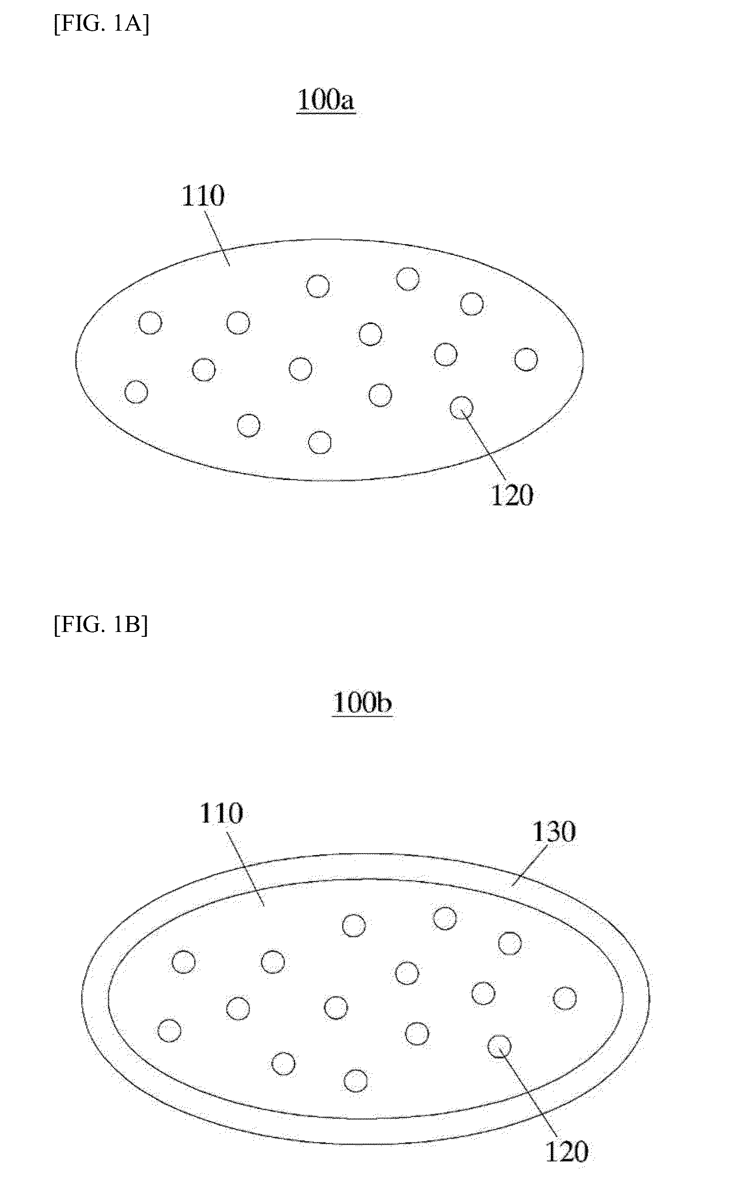
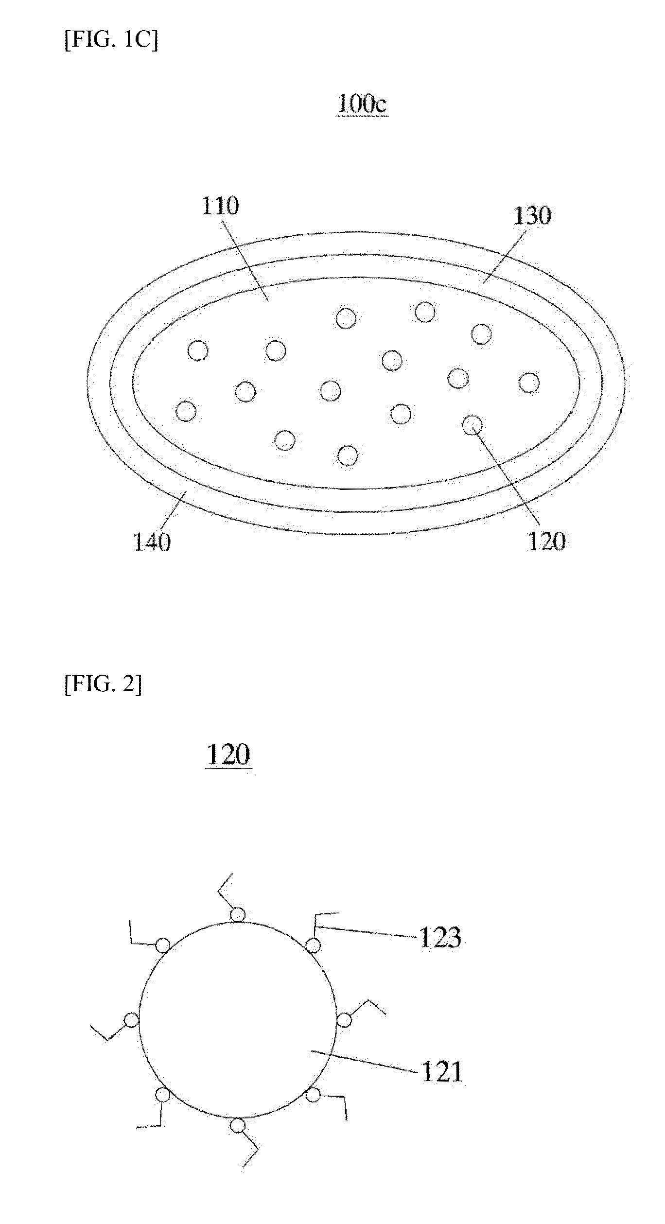
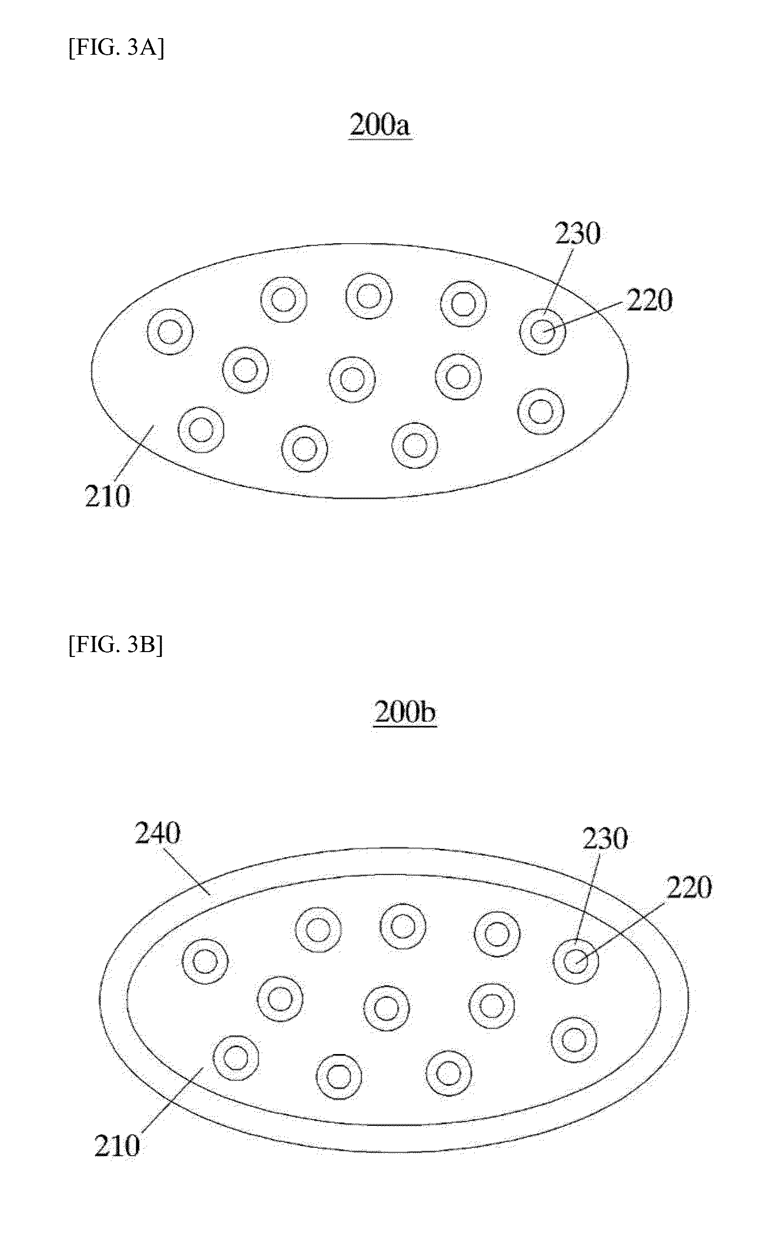
Disclosed is a nanocomposite. The nanocomposite includes a wax particle, at least one nano light-emitting body positioned inside the wax particle, and a silicon oxide protective layer for coating the nano light-emitting body. The nanocomposite can improve light stability and heat/moisture stability of the nano light-emitting body.

Description

CROSS-REFERENCE TO RELATED APPLICATION[0001]This application claims priority to Korean Patent Application No. 10-2012-0126925 filed on Nov. 9, 2012 and Korean Patent Application No. 10-2013-0032896 filed on Mar. 27, 2013, and all the benefits accruing therefrom under 35 U.S.C. §119, the contents of which are incorporated by reference in their entirety.BACKGROUND[0002]1. Field of the Invention[0003]The present invention relates to a nanocomposite, and an optical member and a backlight unit having the optical member.[0004]2. Discussion of Related Art[0005]A nano light-emitting body including a quantum dot or the like is a material having a crystalline structure with a size of several to tens nanometers, and is constituted by hundreds to thousands atoms. Since a band gap increases as sizes of the nano light-emitting bodies are reduced even when the nano light-emitting bodies are formed of the same material, emission properties become different according to the sizes of the nano light-e...

Claims


Application Information

Patent Timeline
Patent Type & Authority Applications(United States)
IPC IPC(8): F21K99/00C09K11/77C09K11/02F21V3/04C09K11/88
CPCF21K9/56F21V3/049F21Y2113/005C09K11/025C09K11/7706C09K11/883G02B6/0065C09K11/02G02B5/0221G02B5/0278G02B6/005G02B6/0051G02B5/201H01L33/507G02B6/0053H01L33/56
Inventor CHOI, JEONG OGKWON, OH KWANKIM, BYEONG CHEOL
Owner LMS
Why Eureka
Try Eureka