Bonding wire and process for manufacturing a bonding wire

a technology of bonding wire and manufacturing process, which is applied in the direction of metallic material coating process, solid-state devices, conductive materials, etc., can solve the problems of difficult copper wire, limited success, and high cost of gold as bonding wire material, and achieve the effect of improving the consistent performance of free air ball

Inactive Publication Date: 2015-11-12
MICROBONDS INC
View PDF0 Cites 20 Cited by
  • Summary
  • Abstract
  • Description
  • Claims
  • Application Information

AI Technical Summary

Benefits of technology

[0039]It is appreciated that for the coating material to provide the function of improving the consistent performance of free air ball (FAB) of copper or silver wire, the coating material itself must be of consistent thickness and remain on the ball during the free air ball (FAB) formation process.
[0040]It was found that a particular type of coating method, using nano-metallic and organic-metallic precursors in liquid solvent, applied to copper wires in solvent was superior to coating fabricated using the electroplated coating method, in terms of providing a consistency in coating thickness and diffusion-free coating layer remaining on the free air ball.

Problems solved by technology

With the rise in the market price for gold metal, the cost of using gold as a bonding wire material has become economically prohibitive.
Users have been seeking to replace gold wire with alternative low-cost metals such as copper, aluminium and silver wires, with limited success due to fundamental technical limitations.
However, copper wire is much harder than gold wire and has the possibility of damaging sensitive chip structures.
Copper wire also oxidizes, it is unstable over time with inconsistent results in wire-bonding.
Furthermore, it has been observed that the point of contact where the bonded ball of the copper wire connects to the aluminium bonding pad of an IC (integrated circuits) chip is subject to high risk of accelerated galvanic corrosion and erosion of the aluminium pad.
Also importantly, current palladium coated copper wires suffer from negative issues related to consistent thickness, distribution and morphology of the palladium on the wire.
This inconsistency results in problems with free air ball formation (FAB), including inconsistent spherical and axi-symmetric free air ball (FAB) formation and insufficient coverage of palladium on the free air ball (FAB).
However, silver wire has an intrinsic technical limitation, which is the inability to form a free air ball (FAB) required for wire-bonding, without the use of a special shielding gas (such as pure nitrogen).
Considering copper based wire as a core bonding wire material, it is noted that palladium coated copper wires have been discussed; however, they suffer from issues related to poor free air ball formation (FAB), high bonded ball hardness, and insufficient coverage of palladium on the free air ball (FAB) surface, resulting in performance and reliability issues.
It is also observed that when there is contamination present on the molten ball, this can also disrupt the formation of the ball and result in off-centered (non axi-symmetric) or malformed (golf club, pointed tip, etc. . . . ) free air balls.
This has the effect of seriously disrupting and lowering the molten surface tension during ball formation.
If the material melts too early, it has the possibility of spreading or ‘wicking’ up the wire during ball formation, with not enough material left in the region of the ball.
Thus a coating material such as aluminium or zinc is not desired, while palladium, nickel, gold and the like meet this condition.
); because when silver reaches the boiling point, the surface will bubble and the resultant surface tension is disrupted.
Hence high melting point materials, such as: Osmium, Iridium and Ruthenium have melting points which exceed the boiling point of silver, and are not suitable as a coating material for silver wire.
It is found that the formation of a ball from a melted wire is a sensitive process and when contaminants, such as oxides or solid residues are present when the silver or copper wire is in the molten state, this has the effect of disrupting the surface.
This prevents the formation of a perfect sphere and the results are malformed and / or off-centered balls.
Materials such as nickel and copper exhibit good surface tension and melting point properties but are not ideal as coating materials because they form an oxide which is present on the ball at the respective melting points.
Hence, suitable coating materials do not form an oxide at temperatures between the melting points of silver or copper, respectively, and the melting point of the coating material itself.
Other noble metals of high surface tension can also be employed, using the same methodology as described above, however with drawbacks regarding the melting point requirement.
It was found in fact that coating materials with a melting temperature higher than the boiling temperature of the core wire material are not feasible because when such a coating material melts, the core material surface would be boiling and bubbling into metal vapour, resulting in an unstable core material-tocoating material interface which again leads to deformed balls.

Method used


Image

  • Bonding wire and process for manufacturing a bonding wire
  • Bonding wire and process for manufacturing a bonding wire
  • Bonding wire and process for manufacturing a bonding wire

Examples


Embodiment Construction

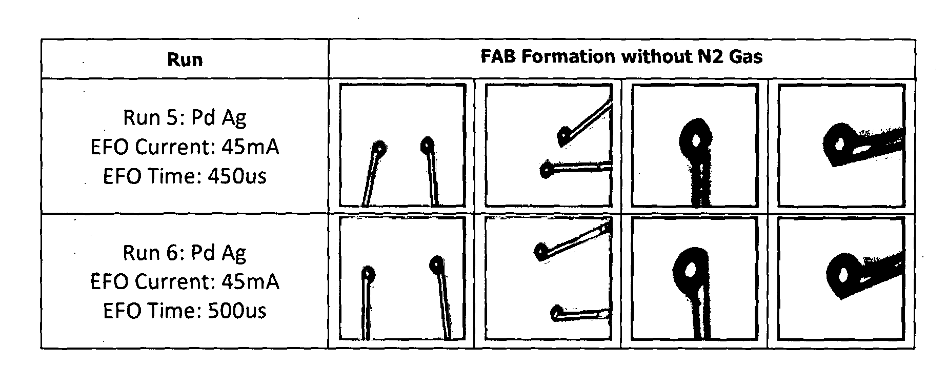
[0069]Coated Silver Wire

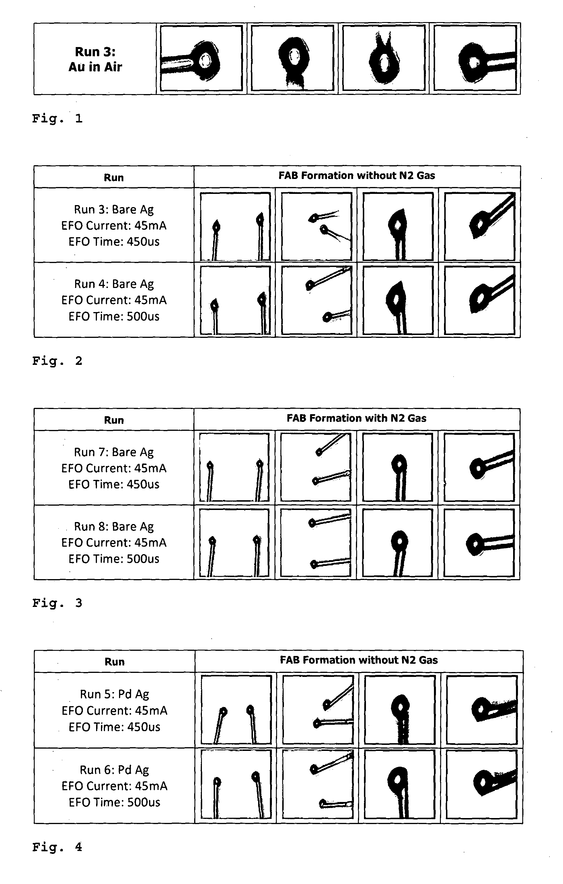
[0070]FIG. 1 shows photos of a free air ball formation of an uncoated gold wire (purity ≧99%). The results are perfect spheres formed by the gold wire in an air environment. The photos show the current standard for ball-bonding, i.e. high purity (≧99%) gold wires forming free air ball in air environment. As shown, the resuiting free air balls are spherical, axi-symmetric, smooth and oxide / contaminant free.

[0071]FIG. 2 shows photos of a free air ball formation of an uncoated silver wire (purity ≧99%) in air. Two runs were performed, one at an electrical flame off (EFO) time of 450 ρs, the other at an EFO time of 500 ρs. Both resulted in poorly formed free air balls (FABs), the resulting FABs are pointed with a severely distorted shape.

[0072]FIG. 3 shows photos of a free air ball formation of an uncoated silver wire (purity ≧99%) in nitrogen gas (N2). Again, two runs were performed, one at an EFO time of 450 μs, the other at an EFO time of 500 ρs. The results w...


PUM

PropertyMeasurementUnit
diameteraaaaaaaaaa
diameteraaaaaaaaaa
thicknessaaaaaaaaaa

Abstract

A bonding wire comprises a core wire generally made of silver or a silver alloy, and the coating material is selected from one or more of: gold, palladium, platinum, rhodium. Alternatively, the core wire is generally made of copper or a copper alloy, and the coating material is selected from one or more of: palladium, platinum, rhodium, iridium, ruthenium. For both core wires, the coating material can be selected from a group of materials with the following characteristics: (1) the materials' melting temperature is higher than the melting temperature of the core wire material, respectively; (2) the materials' molten surface tension is higher than that of the core wire material, respectively; (3) the materials show a high resistance to oxide formation between the melting temperature of the core wire material and the melting temperature of the respective material itself; and (4) the coating material has the additional characteristic that the material's melting temperature is lower than the boiling temperature of the core wire material.

Description

TECHNICAL FIELD[0001]The present invention relates to a bonding wire. Moreover, the present invention relates to a composite bonding wire. Still further, the present invention relates to a composite silver bonding wire. Still further, the present invention relates to a composite copper bonding wire. The present invention also relates to a process for manufacturing a bonding wire.DESCRIPTION OF THE RELATED ART[0002]The increasing global demand for electronics is driving the need for greater performance capabilities of semiconductor chips at lower cost. Currently, the majority of semiconductor chips are internally connected using a thin gold bonding wire. With the rise in the market price for gold metal, the cost of using gold as a bonding wire material has become economically prohibitive. Users have been seeking to replace gold wire with alternative low-cost metals such as copper, aluminium and silver wires, with limited success due to fundamental technical limitations.[0003]Copper w...

Claims


Application Information

Patent Timeline
Patent Type & Authority Applications(United States)
IPC IPC(8): C25D7/06C25D3/50C25D3/54C23C14/34C23C18/31B32B15/01C23C4/08C23C18/16H01B5/02H01B1/02B32B1/00C25D3/48C23C4/12
CPCC25D7/0607Y10T428/12896C25D3/50C25D3/54C23C14/34C23C18/31C23C4/12C23C4/08C23C18/1633H01B5/02H01B1/026H01B1/02B32B1/00B32B15/018B32B15/01Y10T428/12479Y10T428/12875Y10T428/12882Y10T428/12889C25D3/48H01L24/43H01L24/45H01L24/48H01L2224/45138H01L2224/45147H01L2224/45565H01L2224/45644H01L2224/45664H01L2224/45669H01L2224/45673H01L2224/43H01L2224/05624H01L2224/48463H01L2224/85045H01L2224/45139B23K35/3006H01L2224/45015B23K35/0272H01L2224/48599H01L2224/48799H01L2924/00015H01L2224/45144H01L2924/01047H01L2924/3025H01L2224/48624H01L2224/43848H01L2224/48824H01L2224/45676H01L2224/45678H01L2924/00011H01L2924/01206H01L2924/00014H01L2924/20751H01L2924/20752H01L2924/20753H01L2924/20754H01L2924/20755H01L2924/20756H01L2924/20757H01L2924/20758H01L2924/20759H01L2924/2076H01L2924/00H01L2924/20106H01L2924/20107H01L2924/20108H01L2924/20109H01L2924/2011H01L2924/20111H01L2924/01049H01L2924/01006
Inventor LYN, ROBERTPERSIC, JOHN I.
Owner MICROBONDS INC
Why Eureka
Try Eureka