Fluid tight low friction coating systems for dynamically engaging load bearing surfaces

a load bearing surface, fluid-tight technology, applied in the direction of coatings, mechanical equipment, superimposed coating processes, etc., can solve the problems of high frictional force, impeded or interrupted fluid flow, and increased frictional force, so as to reduce the friction coefficient

Inactive Publication Date: 2015-12-10
PRAXAIR ST TECH INC
View PDF6 Cites 11 Cited by
  • Summary
  • Abstract
  • Description
  • Claims
  • Application Information

AI Technical Summary

Problems solved by technology

When the aperture in the gate is partially or completely misaligned with seats, the gate valve is partially or fully closed, and the fluid flow is impeded or interrupted.
The gate and seat components have a tendency to stick, adhere or cold weld to each other, thereby resulting in high frictional forces.
Additionally, the frictional forces can become even larger at higher fluid operating pressures for oil and gas supply and pump lines.
Wear and corrosion is also a problem for oil and gas applications.
As a result, the gate valve must be made of corrosion resistant materials, particularly the seats and gate where corrosion of the surfaces exacerbates wear and frictional problems.
However, such coatings have proven unacceptable, as frictional problems may develop over time and eventually increase to an enhanced level that can result in sticking or uneven movement o the valve gate during operation.
The loss of lubrication can lead to unacceptable valve torques which may lead to local deformation and / or galling of mating surfaces.
While the wear resistant coatings have proven successful at lower operating pressure regimes of 15,000 psi or less, they are typically inadequate as the oil supply and pump lines approach higher pressures.
In particular, gas leakage through the coatings can occur.
Additionally, the coatings lose their lubricity and exhibit galling, thereby rendering such coatings inadequate.
Failure to utilize a coating having adequate fluid impermeability, in combination with adequate wear resistance and lubrication of the gate and seats components can, among other problems, lead to unacceptable galling and potential localized deformation, thereby causing leakage of fluid through the coating and eventually through the valve.

Method used


Image

  • Fluid tight low friction coating systems for dynamically engaging load bearing surfaces
  • Fluid tight low friction coating systems for dynamically engaging load bearing surfaces
  • Fluid tight low friction coating systems for dynamically engaging load bearing surfaces

Examples


example 1

Leak Test for Present Invention—FIG. 6

[0062]A powder blend of a tungsten carbide-cobalt chromium material and a metallic cobalt alloy was employed to produce a coating using a Super D-Gun® coating process. The coating was applied to the test sample having a diameter of approximately 2.8 inches and a thickness of approximately 1.5 inches. A low friction layer of DLC was applied onto the underlying coating. The DLC was applied by PaCVD.

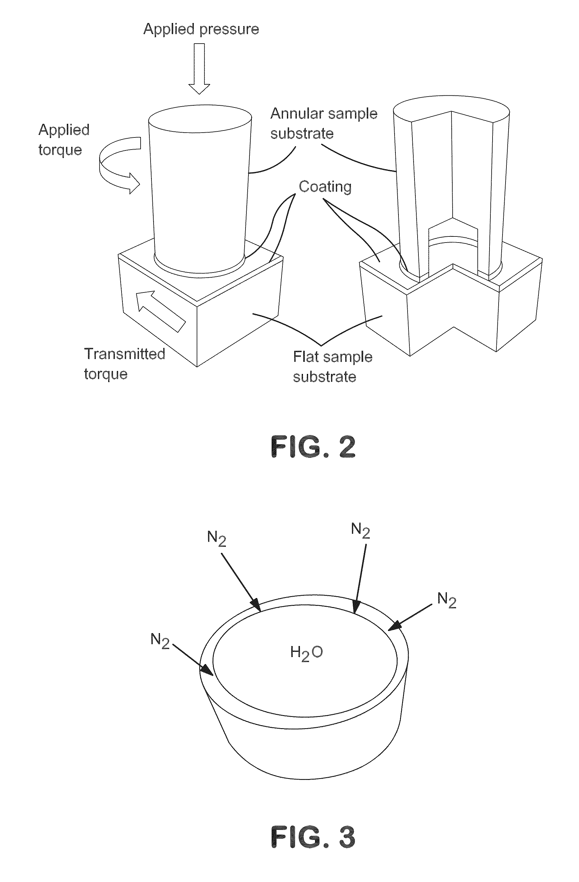
[0063]A high pressure leak test was conducted. No bubbles were observed along the periphery of the tested sample as shown in FIG. 6 at an applied pressure of 10,000 psi after 10 minutes of testing. The lack of bubbles at high pressure was an indication of the ability of the coating with DLC and with sealant to prevent leakage.

example 2

Friction Test for Present Invention at 10,000 Psi—FIG. 9 Orange Line

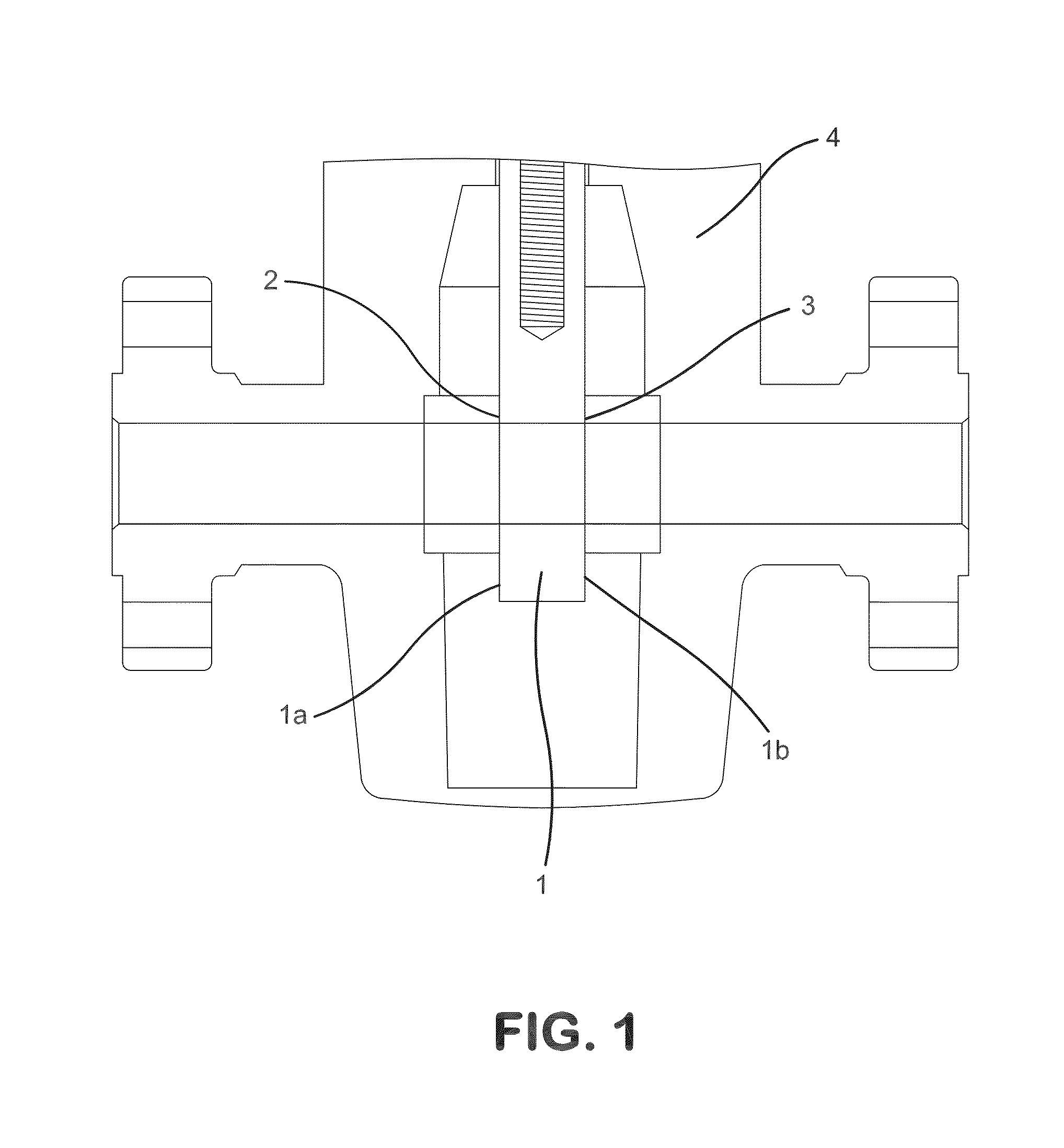
[0064]The frictional behavior of the inventive thermal spray coating system was evaluated using the twist compression test at 10,000 psi contact pressure with no lubrication. The coating to be tested was a Super D-Gun® coating derived from a powder blend of a tungsten carbide-cobalt chromium material and a metallic cobalt alloy. The Super D-Gun® coating was deposited onto the annular sample substrate. The other coating was a HVOF WC—CoCr coating which was deposited onto the flat sample substrate. A low friction layer of DLC was applied onto the underlying Super D-Gun® coating. The DLC was applied by the Pa CVD process.

[0065]When a pressure of 10,000 psi was generated, the annular sample was rotated. Torque transmission between a rotating annular cylinder and a flat sample was measured, and the coefficient of friction was calculated from the ratio of transmitted torque to applied pressure.

[0066]FIG. 9 shows the resul...

example 3

Friction Test for Present Invention at 30,000 Psi—FIG. 10 Orange Line

[0067]The frictional behavior of an inventive thermal spray coating system was evaluated using the twist compression test at 30,000 psi contact pressure with grease. The coating to be tested was a Super D-Gun® coating derived from a powder blend of a tungsten carbide-cobalt chromium material and a metallic cobalt alloy. The Super D-Gun® coating was deposited onto the annular sample substrate. The other coating was a HVOF WC—CoCr coating, which was deposited onto the flat sample substrate. A low friction layer of DLC was applied onto the underlying coating Super D-Gun® coating. The DLC was applied by a PaCVD process.

[0068]When a pressure of 30,000 psi was generated, the annular sample was rotated. Torque transmission between a rotating annular cylinder and a flat sample was measured, and the coefficient of friction was calculated from the ratio of transmitted torque to applied pressure.

[0069]FIG. 10 shows the result...


PUM

PropertyMeasurementUnit
thicknessaaaaaaaaaa
thicknessaaaaaaaaaa
pressuresaaaaaaaaaa

Abstract

A protective coating system is described that is characterized by fluid impermeability and a reduced coefficient of friction. The coating system includes a carbide-based thermal spray composition; a low friction layer; and a sealant impregnated into the low friction layer. Unlike conventional materials, the coating systems of the present invention achieve and maintain sealing surfaces, without adversely impacting lubricity, wear resistance and corrosion resistance during the service life of the coated component.

Description

CROSS REFERENCE TO RELATED APPLICATIONS[0001]This application claims the benefit of priority to U.S. provisional application Ser. No. 62 / 007,724, filed on Jun. 4, 2014, the disclosure of which is incorporated by reference herein in its entirety.FIELD OF THE INVENTION[0002]The present invention generally relates to low friction, fluid impermeable novel protective coatings for a variety of applications. Particularly, the coatings offer low friction and enhanced fluid impermeability for engaging surfaces of gate and seat components.BACKGROUND OF THE INVENTION[0003]Gate valves are typically used when a straight-line flow of fluid and minimum flow restriction are required. Gate valves are an integral part of wellhead assemblies and piping systems utilized in various supply and pump lines, including oil and gas exploration and production where pressures may range from 5,000 to 30,000 psi or greater. Gate valves consist of a valve body located axially in piping through which fluid flows. W...

Claims


Application Information

Patent Timeline
Patent Type & Authority Applications(United States)
IPC IPC(8): C10M103/02C23C4/10F16K25/04F16K3/02F16K25/00C23C4/12C23C4/18
CPCC10M103/02C23C4/122C23C4/10C10M2201/0413F16K3/0227F16K25/005F16K25/04C23C4/18C23C16/27C23C28/00C23C28/042C23C28/044C23C28/046C23C4/067
Inventor KLEYMAN, ARDY S.KNAPP, JAMES K.FEUERSTEIN, ALBERT
Owner PRAXAIR ST TECH INC
Why Eureka
Try Eureka