

Thermoelectric conversion element and thermoelectric conversion module
- Summary
- Abstract
- Description
- Claims
- Application Information
AI Technical Summary
Benefits of technology
Problems solved by technology
Method used
Image

Examples
embodiment 1
[0087]A first embodiment of the invention is described with reference to FIGS. 9A to 12B. In addition, contents which are not described in the embodiment but are described in the Description of Embodiments can be applied to the embodiment, as long as there are no special circumstances.
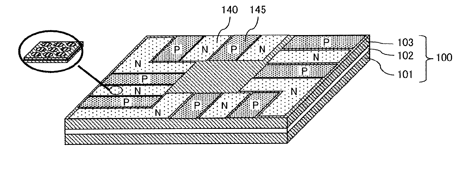
[0088]First, a process of manufacturing a fine particle thermoelectric element that configures a thermoelectric conversion element according to the first embodiment of the invention is described with reference to FIGS. 9A to 9E. FIG. 9A illustrates a step of preparing a SOI substrate 100 obtained by sequentially stacking a SiO2 layer 102 and a monocrystal Si layer 103 on a Si substrate 101. The thickness of the Si layer 103 is set to be 20 nm. Subsequently, a resist film 104 is formed by applying a positive resist for electron beam lithography on the surface of the Si layer 103 of the SOI substrate 100 (FIG. 9B). Subsequently, the resist film 104 is patterned by electron beam lithography and a resist f...
embodiment 2
[0093]A second embodiment of the invention is described. In addition, contents which are not described in the embodiment but are described in the Description of Embodiments and Embodiment 1 can be applied to the embodiment, as long as there are no special circumstances.
[0094]FIGS. 13A and 13B are perspective views for describing a conventional thermoelectric conversion module, FIG. 13A illustrates a state in which plural N layers 240 and plural Players 245 are disposed on plural lower electrodes 250, and FIG. 13B illustrates a state in which plural upper electrodes are disposed in a manner of being deviated to plural lower electrodes so that the plural N layers 240 and the plural P layers 245 illustrated in FIG. 13A are all connected in series. In the thermoelectric conversion module, with respect to the N layers and the P layers all connected in series, for example, if an anode side of the power supply is connected to the extraction electrode 250 on the lowermost right side of the ...
PUM
 Abstract
Description
Claims
Application Information