Devices, systems and methods for monitoring hip replacements

a technology for hip replacement and monitoring devices, applied in the field of hip replacements, can solve the problems of improper operation of hip joint, patient discomfort, and various complications, and achieve the effect of being easily incorporated into bone cement or

Inactive Publication Date: 2016-02-04
CANARAY MEDICAL INC
View PDF10 Cites 38 Cited by
  • Summary
  • Abstract
  • Description
  • Claims
  • Application Information

AI Technical Summary

Benefits of technology

[0024]The integrity of the partial or total hip prosthesis can be wirelessly interrogated and the results reported on a regular basis. This permits the health of the patient to be checked on a regular basis or at any time as desired by the patient and / or physician.
[0025]Within further embodiments, each of the sensors contains a signal-receiving circuit and a signal output circuit. The signal-receiving circuit receives an interrogation signal that includes both power and data collection request components. Using the power from the interrogation signal, the sensor powers up the parts of the circuitry needed to conduct the sensing, carries out the sensing, and then outputs the data to the interrogation module. The interrogation module acts under control of a control unit which contains the appropriate I / O circuitry, memory, a controller in the form of a microprocessor, and other circuitry in order to drive the interrogation module. Within yet other embodiments the sensor (e.g., an acceleration sensor, a tilt sensor, a vibration sensor, a shock sensor, a rotation sensor, a pressure sensor, a contact sensor, a position sensor, a chemical microsensor, a tissue metabolic sensor, or a mechanical stress sensor) are constructed such that they may readily be incorporated into or otherwise mechanically attached to the hip prosthesis (e.g., by way of a an opening or other appendage that provides permanent attachment of the sensor to the hip prosthesis) and / or readily incorporated into the bone cement or the tissues that surround the hip prosthesis.

Problems solved by technology

Unfortunately, when a total hip is inserted, various complications may arise over time.
For example, as shown in FIG. 3, there may be wear between the femoral head and the acetabular liner, which leads to improper operation of the artificial hip joint.
In addition, the patient may experience inflammation and pain if there is slight movement or dislocation of any of the components.
Depending on the types of materials used for the acetabular liner (if present, as in THR) and the femoral head (both THR and Hemi-arthroplasty), there may be wear in the acetabular liner and / or the femoral head which results in loosening or partial (or full) dislocation of the joint, may degrade the performance of the hip, result in difficulty in movement and ambulation, and may cause pain and inflammation for the patient.
Erosion of the bone around the implant may be caused by material debris (metal, ceramic, and / or polyurethane fragments) generated by friction between the femoral head and acetabular cup entering the tissues surrounding the implant and causing inflammation and bone loss.
Other potential causes of inflammation and osteolysis are implant vibration and motion, mechanical wear and tear, lack of biocompatibility between the implant materials and the surrounding bone, metal allergy, and lack of biocompatibility between the bone cement and the surrounding bone.
Unfortunately, most of the patient's recuperative period occurs between hospital or office visits.
It can, therefore, be very difficult to accurately measure and follow full joint range of motion (ROM can change depending on pain control, degree of anti-inflammatory medication, time of day, recent activities, and / or how the patient is feeling at the time of the examination), “real life” prosthesis performance, patient activity levels, exercise tolerance, and the effectiveness of rehabilitation efforts (physiotherapy, medications, etc.) from the day of surgery through to full recovery.
For much of this information, the physician is dependent upon patient self-reporting or third party observation to obtain insight into post-operative treatment effectiveness and recovery and rehabilitation progress; in many cases this is further complicated by a patient who is uncertain what to look for, has no knowledge of what “normal / expected” post-operative recovery should be, is non-compliant, or is unable to effectively communicate their symptoms.
Sudden increases in strain may indicate that too much stress is being placed on the replacement prosthesis, which may increase damage to the body.
For example, a gradual, long-term decrease in strain may cause bone reabsorption around the implant, leading to loosening of the prosthesis or fractures in the bone surrounding the prosthesis.

Method used


Image

  • Devices, systems and methods for monitoring hip replacements
  • Devices, systems and methods for monitoring hip replacements
  • Devices, systems and methods for monitoring hip replacements

Examples


embodiment 1

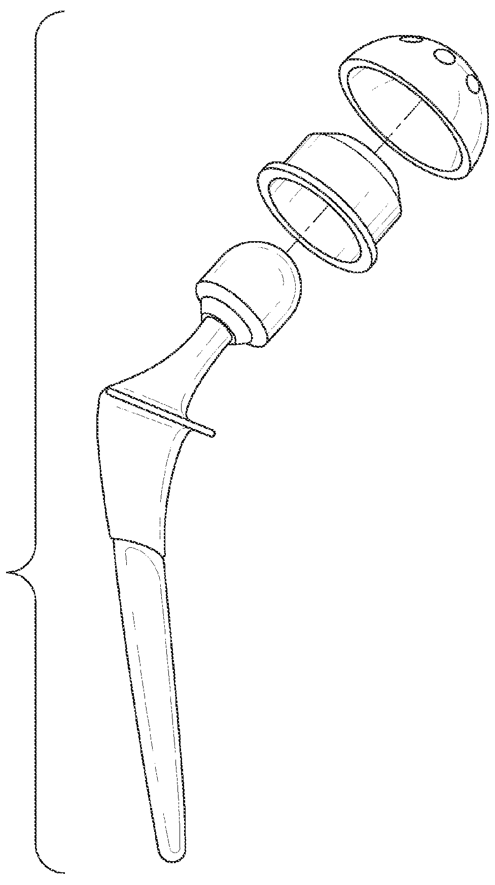
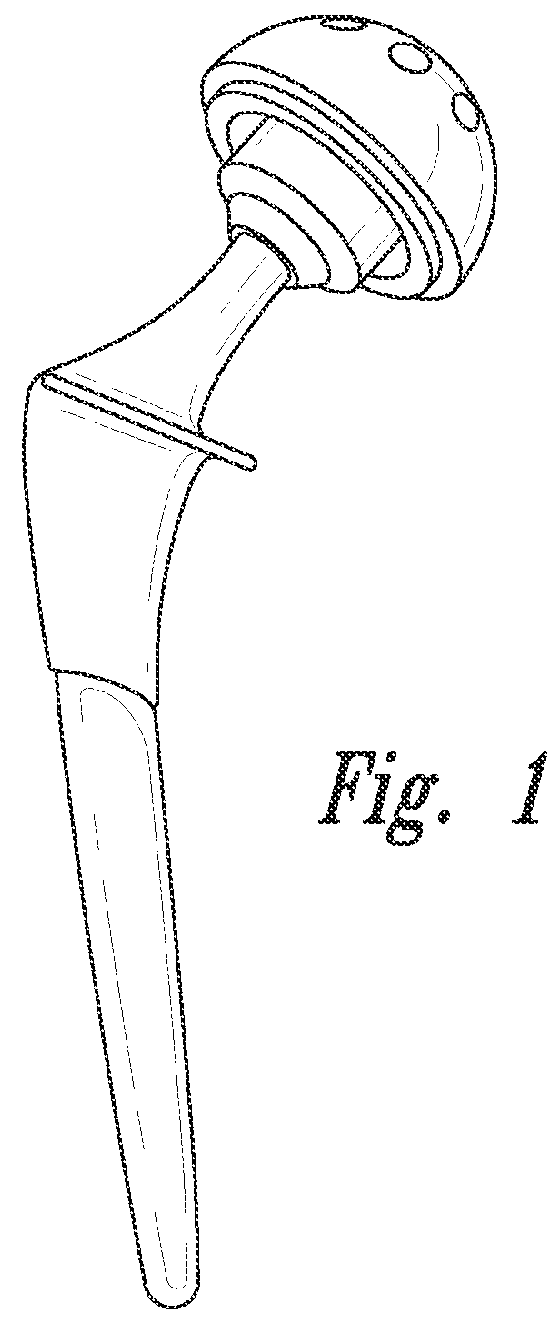
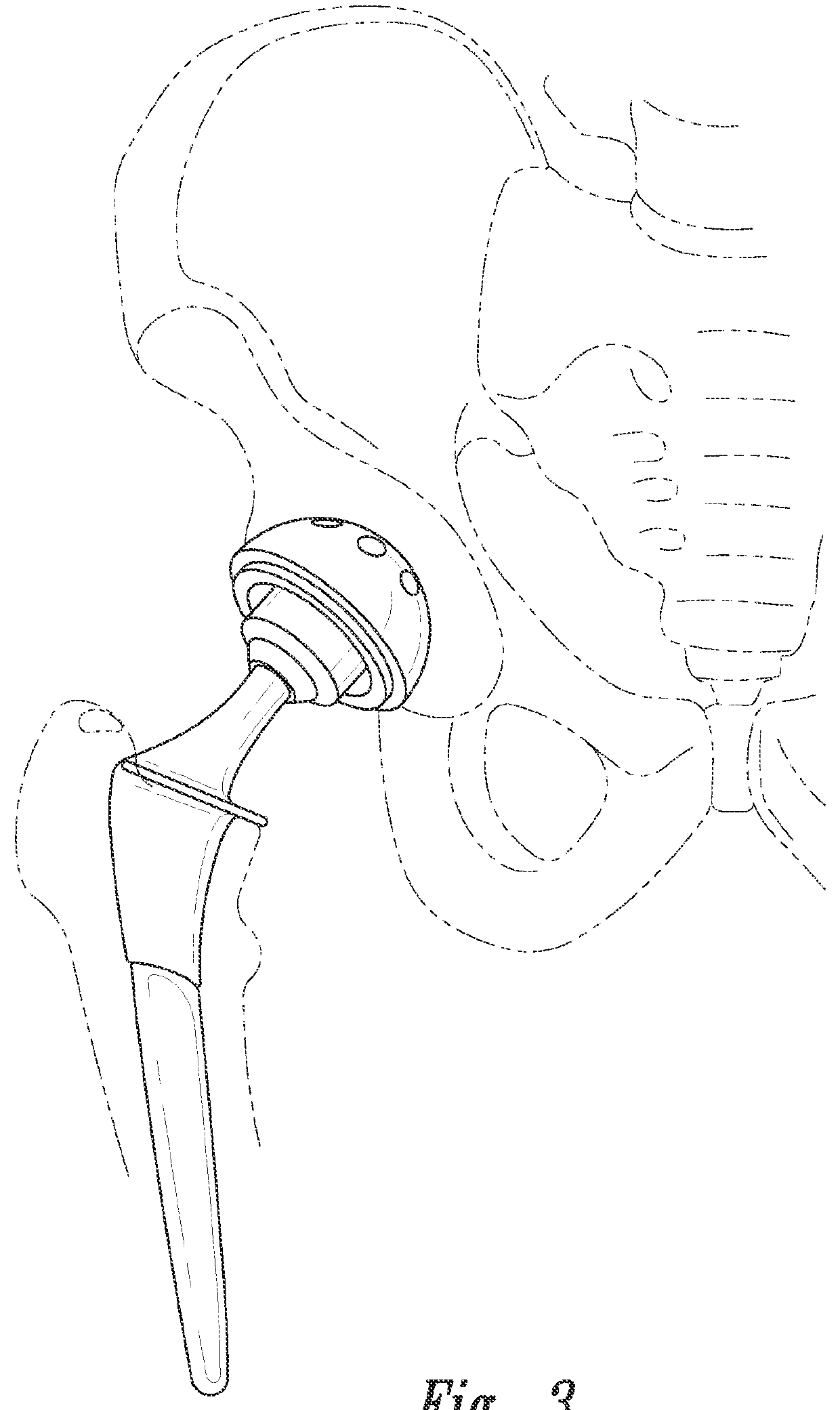
[0132]2) The hip replacement prosthesis of embodiment 1 wherein the plurality of sensors includes a sensor on the femoral stem.

[0133]3) The hip replacement prosthesis of embodiment 1 wherein the plurality of sensors includes a sensor on the femoral head.

[0134]4) The hip replacement prosthesis of embodiment 1 wherein the plurality of sensors includes a sensor on the acetabular assembly.

[0135]5) The hip replacement prosthesis according to any one of embodiments 1 to 4 wherein said sensor is selected from the group consisting of accelerometers, pressure sensors, contact sensors, position sensors, chemical microsensors, tissue metabolic sensors, mechanical stress sensors and temperature sensors.

embodiment 5

[0136]6) The hip replacement prosthesis wherein said accelerometer detects acceleration, tilt, vibration, shock and or rotation.

[0137]7) The hip replacement prosthesis of embodiment 1 wherein the plurality of sensors includes contact sensors positioned between the femoral head and the acetabular assembly.

[0138]8) The hip replacement prosthesis of embodiment 1 wherein the plurality of sensors includes a plurality of contact sensors positioned on the outer surface of the acetabular assembly.

[0139]9) The hip replacement prosthesis of embodiment 1 wherein the plurality of sensors includes a plurality of contact sensors positioned on the outer surface of the acetabular assembly.

[0140]10) The hip replacement prosthesis of embodiment 1 wherein the plurality of sensors includes a plurality of strain sensors positioned between the femoral head the acetabular assembly.

[0141]11) The hip replacement prosthesis of embodiment 1 wherein the plurality of sensors includes accelerometers positioned ...

embodiment 7

[0143]13) The hip replacement prosthesis of embodiment 7 further including strain sensors positioned between the acetabular liner and the acetabular shell.

[0144]14) A medical device, comprising a femoral stem and a plurality of sensors coupled to said femoral stem.

[0145]15) A medical device, comprising a femoral head and a plurality of sensors coupled to said femoral head.

[0146]16) A medical device, comprising an acetabular assembly and a plurality of sensors coupled to said acetabular assembly.

[0147]17) The medical device according to any one of embodiments 14 to 16, wherein said sensors are placed within and on the surface of said medical device.

[0148]18) The medical device according to any one of embodiments 14 to 17 wherein said sensor is selected from the group consisting of accelerometers, pressure sensors, contact sensors, position sensors, chemical microsensors, tissue metabolic sensors, mechanical stress sensors and temperature sensors.


PUM


Abstract

Hip replacement prosthesis are provided, comprising a femoral stem, a femoral head coupled to the femoral stem, and an acetabular assembly coupled to the femoral head, and a plurality of sensors coupled to at least of the femoral stem, femoral head, and acetabular assembly.

Description

CROSS-REFERENCE TO RELATED APPLICATION[0001]This application claims the benefit under 35 U.S.C. §119(e) of U.S. Provisional Patent Application No. 61 / 789,170 filed Mar. 15, 2013, which application is incorporated herein by reference in its entirety.BACKGROUND[0002]1. Field of the Invention[0003]The present invention relates generally to hip replacements, and more specifically, to devices and methods for monitoring the performance of total and partial hip replacements.[0004]2. Description of the Related Art[0005]Hip replacement is one of the most common orthopedic surgical procedures. It may be carried out when the patient loses sufficient use of the hip, typically due to injury, avascular necrosis of the hip, or for the treatment of extreme and / or constant joint pain (e.g., due to various types of arthritis (such as rheumatoid or osteoarthritis)).[0006]Hip replacement can take a variety of different forms. In total hip replacement (THR), both the femoral head and the acetabulum are ...

Claims


Application Information

Patent Timeline
Patent Type & Authority Applications(United States)
IPC IPC(8): A61B5/00A61F2/34A61F2/36A61F2/46
CPCA61B5/4851A61B5/0022A61F2/34A61F2/36A61F2002/4674A61F2002/3067A61F2002/4666A61F2002/4668A61F2002/4672A61F2/4657A61F2/32A61F2002/467G16H40/40
Inventor HUNTER, WILLIAM, L.
Owner CANARAY MEDICAL INC
Why Eureka
Try Eureka