Fuel cell system ion exchanger

Active Publication Date: 2016-02-11
HONDA MOTOR CO LTD
View PDF1 Cites 1 Cited by
  • Summary
  • Abstract
  • Description
  • Claims
  • Application Information

AI Technical Summary

Benefits of technology

[0019]In the present invention, the water supply port is provided at the lower position of the apparatus body, and the water discharge port is provided at the upper position of the apparatus body. In the structure, since the water flows inside the apparatus body, from lower to upper positions, i.e., in the direction opposite to the gravity direction, non-uniform flow of the water within the apparatus body is suppressed. Further, the time period of contact between the water flowing in the direction opposite to the gravity direction and the ion exchange resin becomes long, and thus, ion exchange is performed reliably to achieve improvement in the ion exchange efficiency.
[0020]Further, the air container is provided at the upper position of the apparatus body, for containing the air mixed into the apparatus body in a concentrated manner. In the structure, it is possible to suppress the air from flowing downstream of the ion exchanger. Therefore, it becomes possible to suppress degradation of the performance of the water pump due to air entailment, oxidation of reforming catalyst due to mixing of the air into the reformer, and instabil

Problems solved by technology

Therefore, the equipment has a significantly large size as a whole.
Further, since the water treatment unit is provided separately, size reduction cannot be achieved.
Moreover, when the equipment is configured initially, or in the case where the equipment has not been used for a long period of time, air tends to be stagnant in the air return mechanism 3a, and the air ca

Method used


Image

  • Fuel cell system ion exchanger
  • Fuel cell system ion exchanger
  • Fuel cell system ion exchanger

Examples


Embodiment Construction

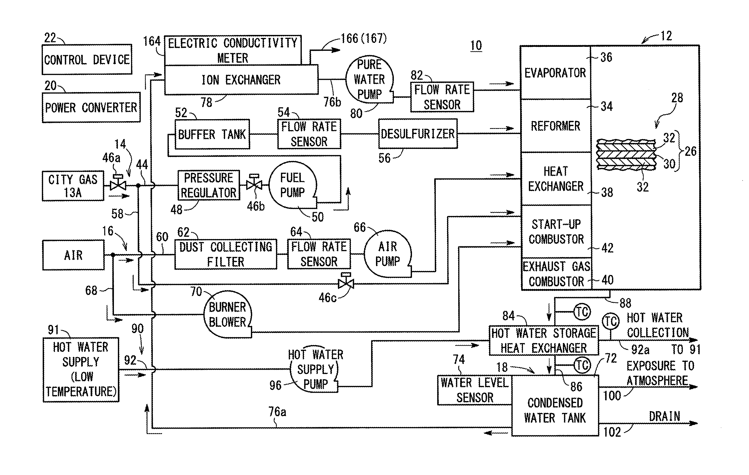
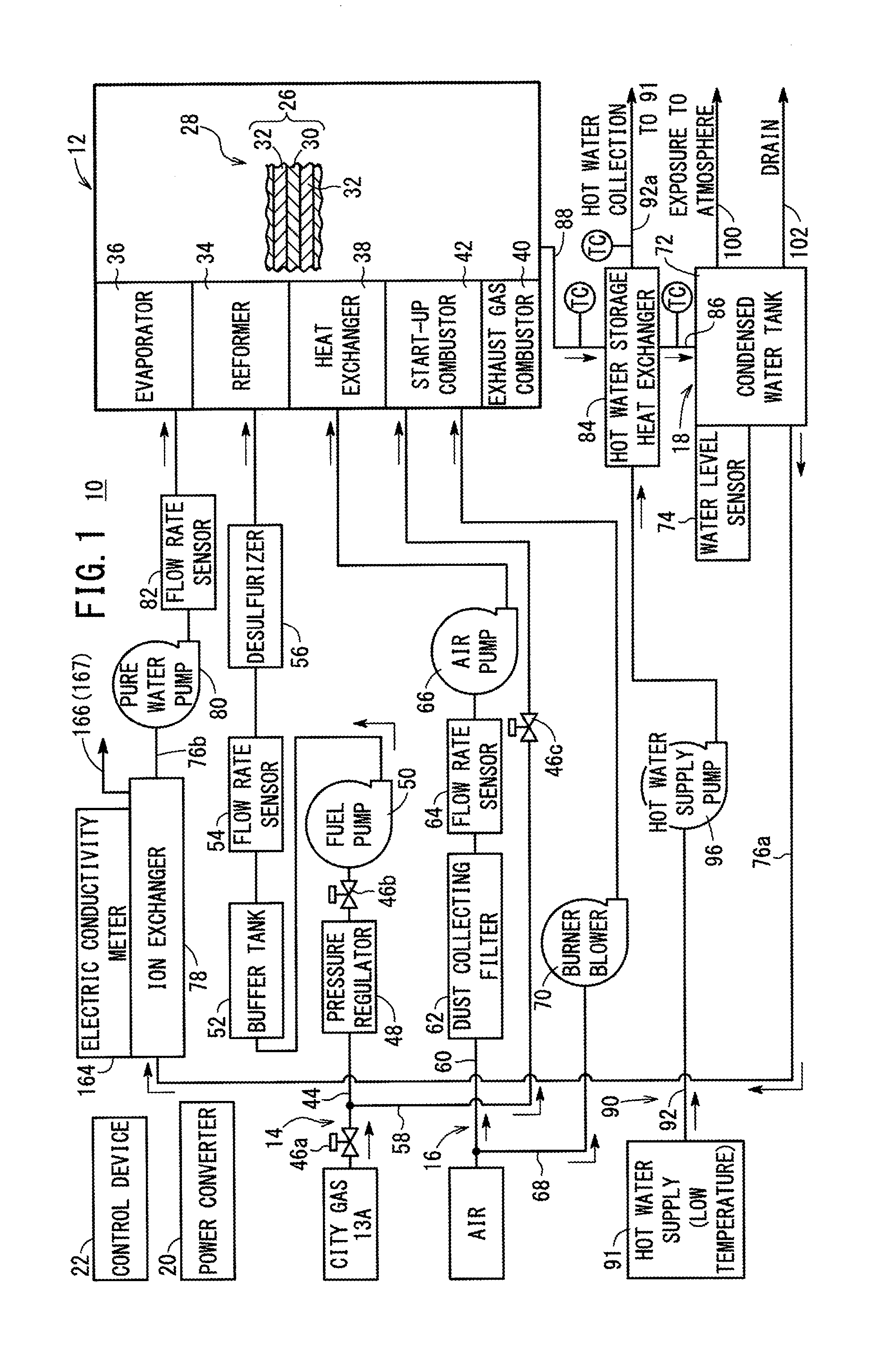
[0039]As shown in FIG. 1, a fuel cell system 10 including an ion exchanger (described later) according to a first embodiment of the present invention is used in a stationary application. However, the fuel cell system 10 can be used in various applications. For example, the fuel cell system 10 may be mounted in a vehicle.

[0040]The fuel cell system 10 includes a fuel cell module (SOFC module) 12 for generating electrical energy in power generation by electrochemical reactions of a fuel gas (e.g., mixed gas of a hydrogen gas, methane, and carbon monoxide) and an oxygen-containing gas (e.g., air), a fuel gas supply apparatus 14 for supplying a raw fuel (e.g., city gas) chiefly containing hydrocarbon as the fuel gas to the fuel cell module 12, an oxygen-containing gas supply apparatus 16 for supplying the oxygen-containing gas to the fuel cell module 12, a water supply apparatus 18 for supplying water to the fuel cell module 12, a power converter 20 for converting the direct current elec...


PUM


Abstract

An ion exchanger includes an apparatus body having a lower filter and an upper filter. Ion exchange resin fills a space between the lower filter and the upper filter. A water supply port is provided at a lower position of the apparatus body, and a water discharge port is provided at an upper position of the apparatus body. An air container is provided at an upper position of the apparatus body, and an electric conductivity meter is provided in the air container at a position above the water discharge port.

Description

TECHNICAL FIELD[0001]The present invention relates to a fuel cell system ion exchanger. Water contained in an exhaust gas discharged from a fuel cell for generating electricity by electrochemical reactions of a fuel gas and an oxygen-containing gas passes through the fuel cell system ion exchanger.BACKGROUND ART[0002]Typically, a solid oxide fuel cell (SOFC) employs a solid electrolyte of ion-conductive oxide such as stabilized zirconia. The solid electrolyte is interposed between an anode and a cathode to form an electrolyte electrode assembly (MEA). The electrolyte electrode assembly is interposed between separators (bipolar plates). In use, normally, predetermined numbers of the electrolyte electrode assemblies and the separators are stacked together to form a fuel cell stack.[0003]As the fuel gas supplied to the fuel cell, normally, a hydrogen gas produced from hydrocarbon raw material by a reformer is used. In general, in the reformer, a reforming raw gas is obtained from a hyd...

Claims


Application Information

Patent Timeline
IPC IPC(8): H01M8/06
CPCH01M8/0687H01M2250/10H01M8/0606C02F1/42C02F1/50C02F2209/05G01N27/08H01M8/04022H01M8/04067H01M8/04097H01M8/04164H01M8/04201H01M8/0432H01M8/04656H01M8/04686H01M8/04776H01M8/0618H01M2008/1293Y02E60/50Y02B90/10
Inventor YUZURIHA, AKIHITO
Owner HONDA MOTOR CO LTD
Why Eureka
Try Eureka