Method, computer program product & system

Inactive Publication Date: 2016-02-18
AB SKF
View PDF6 Cites 12 Cited by
  • Summary
  • Abstract
  • Description
  • Claims
  • Application Information

AI Technical Summary

Benefits of technology

The invention provides a method for digitally demodulating and filtering acoustic emissions using digital circuitry instead of conventional analog methods. This avoids the need for precise analog filters and reduces the number of operational amplifiers required, resulting in lower current and smaller circuitry. The digital method also has a wider dynamic range and is better suited for lossy transmission paths. By transmitting and displaying only the digitally demodulated signal, the amount of data that needs to be transmitted, displayed, and processed is reduced, leading to faster transmission, processing, and battery life extension.

Problems solved by technology
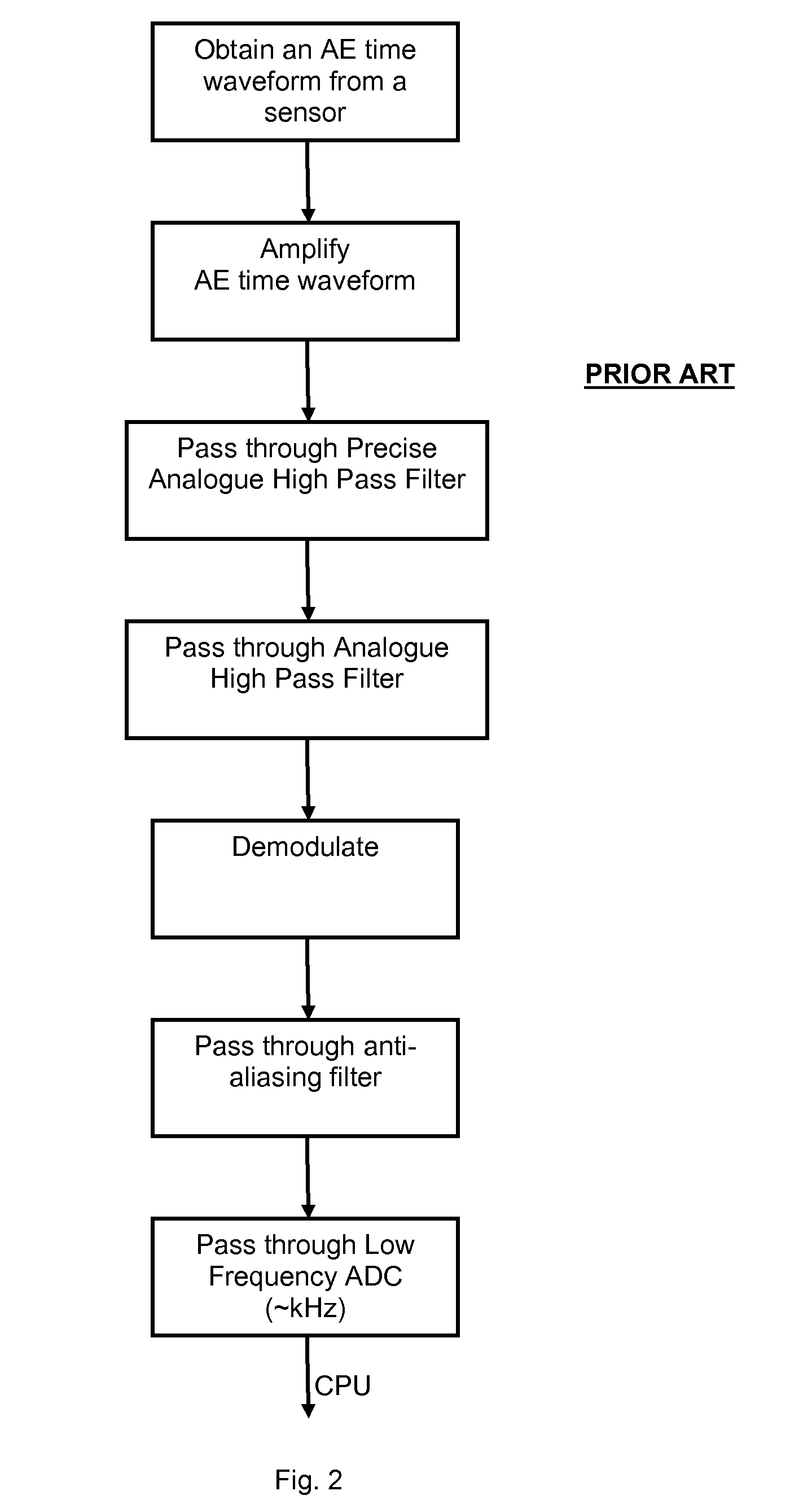
Components such as rolling-element bearings are often used in critical applications, wherein their failure in service would result in significant commercial loss to the end-user.
Fatigue failure of a rolling element bearing results from progressive flaking or pitting of the surfaces of the rolling elements and of the surfaces of the corresponding bearing races.
The flaking and pitting may cause seizure of one or more of the rolling elements, which in turn may generate excessive heat, pressure and friction.
However, this type of life prediction is considered inadequate for the purpose of maintenance planning for several reasons.
Another reason is that a bearing's residual life may be radically compromised by short-duration events or unplanned events, such as overloads, lubrication failures, installation errors, etc.
Yet another reason is that, even if nominal operating conditions are accurately reproduced in service, the inherently random character of the fatigue process may give rise to large statistical variations in the actual residual life of substantially identical bearings.
Furthermore, a lubrication film can be compromised by excessive load, low viscosity of the lubricant or contamination of the lubricant with particulate material, or a lack of lubricant.
Such conventional analogue enveloping systems have the following disadvantages: high current, low dynamic range, physically large, unsuitable for inclusion in an application-specific integrated circuit (ASIC) and poor temperature performance.
This can however result in long transmission and display times and the data can be difficult to display or interpret.
The transmission, display and interpretation of such data can require a significant amount of energy, time and expertise, and consequently decreases the rate at which measurements and analyses can be made.

Method used


Image

  • Method, computer program product & system
  • Method, computer program product & system
  • Method, computer program product & system

Examples


Embodiment Construction

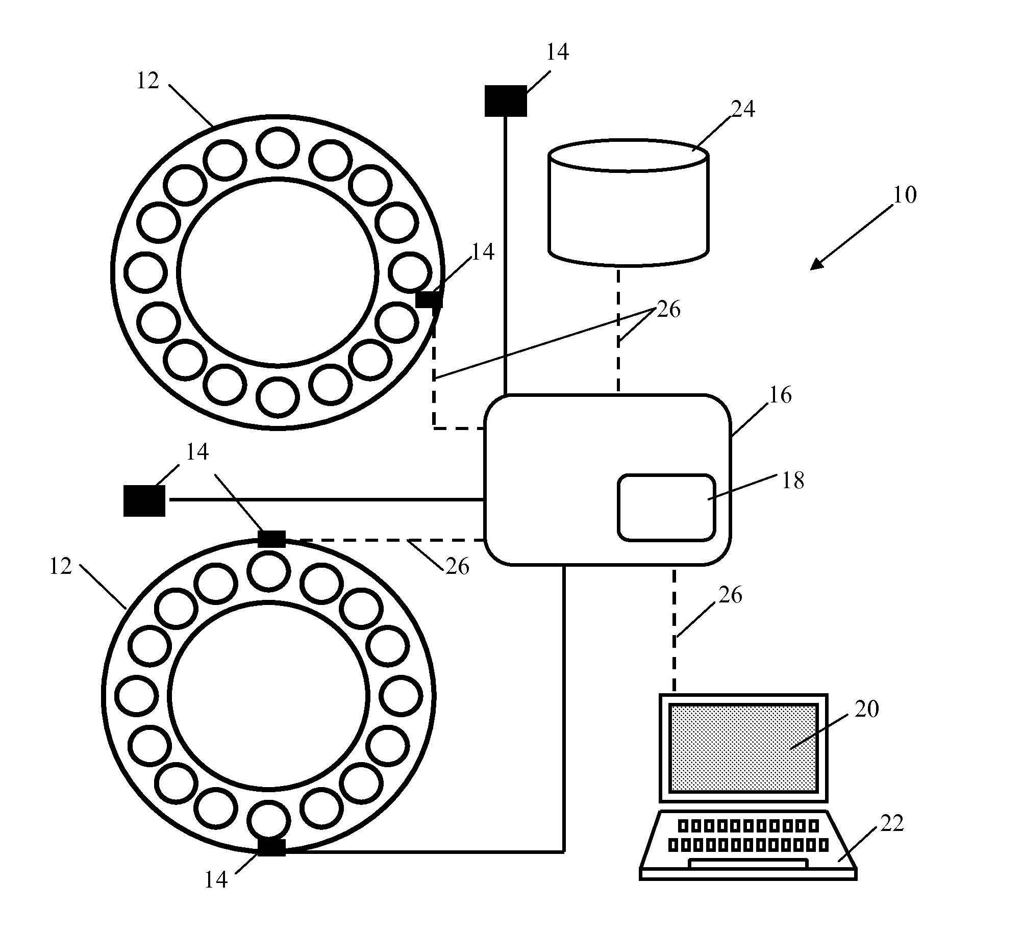
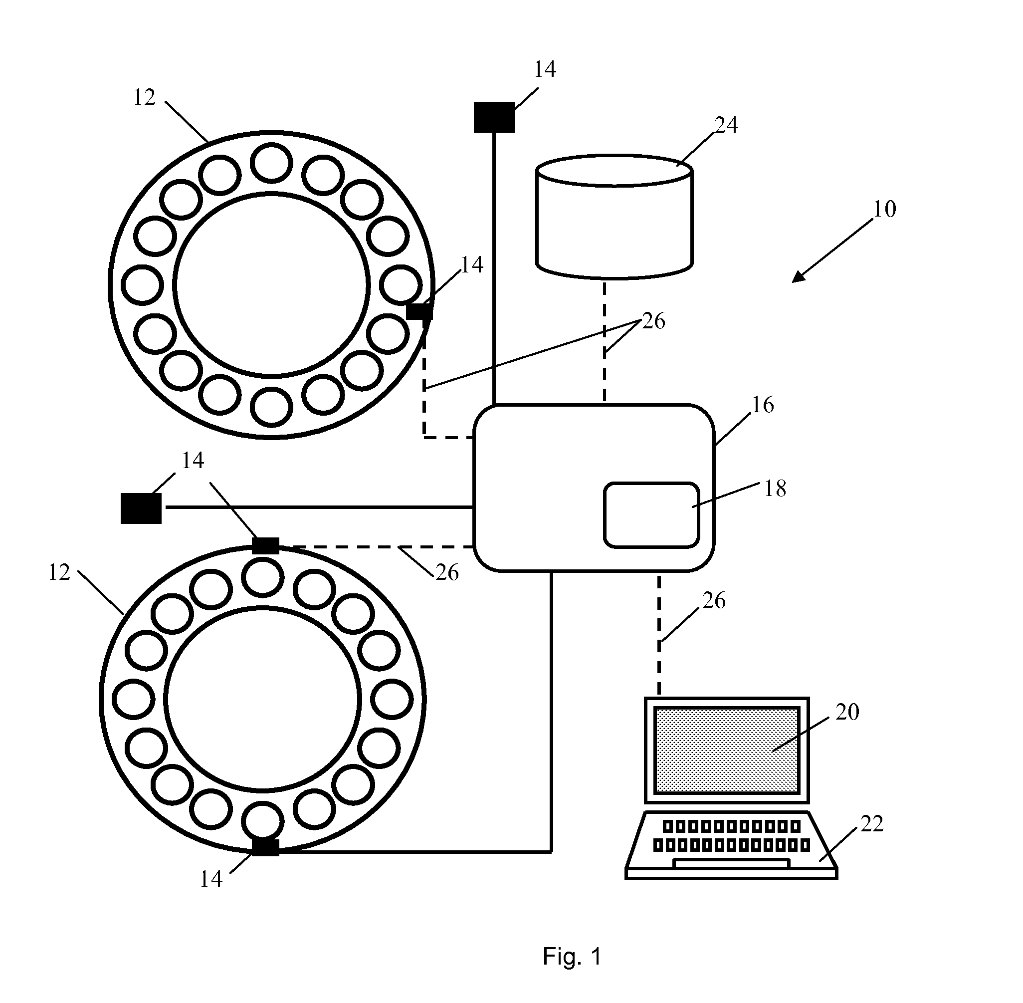
[0040]FIG. 1 shows a system 10 for monitoring the condition, and optionally predicting the residual life of a plurality of bearings 12 during their use. The illustrated embodiment shows two rolling element bearings 12, the system 10 according to the present invention may however be used to monitor and optionally predict the residual life of one or more components of any type, and not necessarily all of the same type or size. The system 10 comprises a plurality of sensors 14 configured to obtain data concerning one or more of the factors that influence the residual life of each bearing 12. A sensor 14 may be integrated with a bearing 12, it may be placed in the vicinity of the bearing 12 or remotely from the bearing.

[0041]The inner ring and / or outer ring of a bearing 12, which can be monitored using a system or method according to an embodiment of the invention, may be of any size and have any load-carrying capacity. An inner ring and / or an outer ring may for example have a diameter ...


PUM


Abstract

A method for processing data obtained from a condition monitoring system, the method including steps of (a) obtaining an Acoustic Emission time waveform from at least one sensor and (b) digitally demodulating the Acoustic Emission time waveform.

Description

CROSS REFERENCE TO RELATED APPLICATION[0001]This is a United States National Stage Application claiming the benefit of International Application Number PCT / EP2013 / 057178 filed on 05 Apr. 2013 (Apr. 05, 2013), which is incorporated herein by reference in its entirety.TECHNICAL FIELD[0002]The present invention concerns a method, system and computer program product for processing data obtained from a condition monitoring system, such a condition monitoring system for monitoring and optionally predicting the residual life of a component, such as a bearing, i.e. for predicting when it is necessary or desirable to service, replace or refurbish (re-manufacture) the component.BACKGROUND OF THE INVENTION[0003]Condition monitoring is the process of determining the condition of machinery while in operation. Condition monitoring enables the repair of problem components prior to failure and not only helps plant personnel reduce the possibility of catastrophic failure, but also allows them to ord...

Claims


Application Information

Patent Timeline
IPC IPC(8): G01N29/14G01M13/04
CPCG01N29/14G01M13/045G01N29/42G01N29/4454G05B23/0283G01N2291/0258G01N2291/2696
Inventor MCGOOGAN, GERARD
Owner AB SKF
Why Eureka
Try Eureka