Liner-provided cap and cap-provided threaded container

a technology of threaded containers and liner caps, which is applied in the direction of caps, applications, liquid handling, etc., can solve the problems of unfavorable material yield rate, poor oxygen barrier property of produced caps, and increase in the weight of the liner, etc., and achieves low opening torque, excellent openability, and easy engagement with the cap shell

Inactive Publication Date: 2016-02-25
UNIVERSAL CAN CORP
View PDF4 Cites 10 Cited by
  • Summary
  • Abstract
  • Description
  • Claims
  • Application Information

AI Technical Summary

Benefits of technology

[0076]In other words, for the liner-provided cap and the cap-provided threaded container according to the present invention, the soft layer is concentric with the rigid sheet and is formed in an annular or disk shape with a diameter smaller than that of the rigid sheet so that the soft layer can be brought into contact with at least the mouth. Hence, even if the soft layer is deformed during capping, the soft layer does not contact with the inside surface of the cap shell, whereby excellent openability can be obtained while maintaining low opening torque. The liner can be readily engaged with the cap shell, and high sealing property and suitability for liner setting can be obtained.
[0077]For the liner-provided cap and the cap-provided threaded container according to the present invention, an adhesive layer disposed between the intermediate layer having gas-barrier property and the sliding layer or the sealing layer to adhere to each other is provided, whereby a good adhesive property of the intermediate layer via the adhesive layer can be obtained, and excellent producibility can be obtained by openability due to the sliding layer, sealing property due to the sealing layer, improved gas-barrier property due to the intermediate layer, and high adhesive property due to the adhesive layer.

Problems solved by technology

These methods are disadvantageous in that although manufacturing facilities for use in the disk insertion method or the disk insertion adhesion method are relatively inexpensive, a produced cap often exhibits inferior oxygen barrier property because of a, single layered liner.
In addition, since a disk-like liner is punched out from the sheet, the punched waste of the liner is generated, resulting in unfavorable poor yield rates from the material.
In addition, since the liner has a sheet configuration, the central portion of the layer, where it is not involved in sealing property, cannot be reduced, resulting in a weight increase of the liner.
On the other hand, in the lining method, although a liner material can be placed at the seal portion only, sanitation may be poor because the main material is vinyl chloride sol (PVC paste).
The in-shell mold method has a relatively high efficiency for the amount of the liner material used, and is suitable for mass production, whereas it is not appropriate for low-volume production.
Since the liner material is extruded from an extruder and cut in a semi-molten state, a material having poor extrusion moldability cannot be used, whereby the available material is limited.
However, this method includes many steps such as applying a liner adhesion coating material onto an aluminum sheet; punching out the resulting sheet; subjecting to a drawing process; and heat-adhering the liner material (heat-adhesion of liner and shell), which increase cost and is thereby not practical.
Also, compared to resin (such as PP resin), recycling of the punched waste of an aluminum sheet is not easy.
In addition to above, there are other methods for inserting an expanded PE (polyethylene) disk, and for heat-molding a cast vinyl chloride sol (PVC paste), which are disadvantageous in cost and sanitation, and are thereby limited in use.
However, since the liner material is completely adhered to a cap shell, the friction force between the mouth and the cap shell of the container when the cap is opened is relatively large.
Consequently, a torque required for opening is high, which occasionally causes difficulty in opening.
However, it is difficult to control the amount of bleeding of the lubricant.
When the amount of bleeding is too small, the lubricant cannot work sufficiently, resulting in high torque required for opening.
Although the two-layer sheet liner exhibits advantageous sealing property, it does not have sufficient sealing property with respect to the content required for a long-term storage.
Undesirably, a material having particularly poor gas-barrier property must be used for a cap liner for high temperature filling goods or a liner for retort treatment.
However, the techniques described in these Patent Documents have several disadvantages for the liner material.
With this arrangement, the irregularities of the bottle mouth cannot be covered sufficiently because of the hardness of the deposited layer, whereby sufficient sealing property cannot be obtained.
This method can be employed for production but results in high cost.
For example, a manufacturing apparatus of a large-scale is required for insert molding, and the production speed is significantly reduced, which leads to an expensive cap.
Likewise, adhesion, application, and deposition are also costly.
In addition, these cap liners cannot withstand retort treatment.
Hence, the smell of the crosslinking agent emanates from the liner, which is not suitable for food application.
Also, because of poor slidability, such liner is not suitable for the liner of the cap being rotated and opened such as a ROPP (roll on pilfer proof) cap.
However, when the container is at a normal pressure or a reduced pressure, the intimate contact fails between the cap shell and the liner, thereby introducing the problem of not acquiring the barrier effect of the nonvolatile liquid.
However, as described above, the liner is fully adhered to the cap shell, which has the disadvantage of high opening torque.
In this method, it is difficult to control the amount of bleeding of the lubricant.
However, the liner material has insufficient oxygen barrier property with respect to the content required for a long-term commodity cycle since the liner is not in intimate contact with the cap's top surface and thereby gas such as oxygen passed out through the liner causes the content to degrade.

Method used


Image

  • Liner-provided cap and cap-provided threaded container
  • Liner-provided cap and cap-provided threaded container
  • Liner-provided cap and cap-provided threaded container

Examples


first embodiment

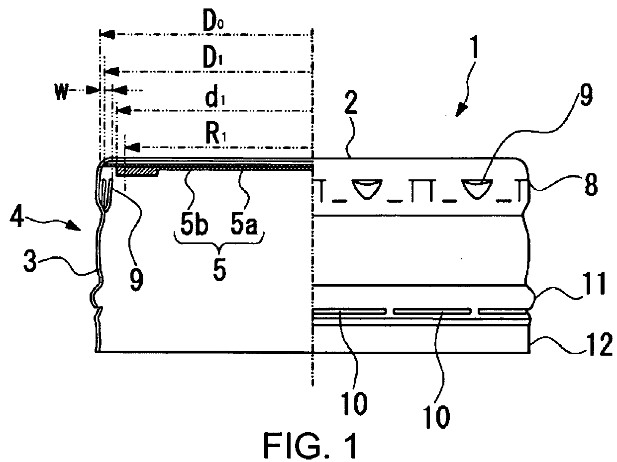
[0085]Hereinafter, an embodiment of the liner-provided cap and the cap-provided threaded container according to the present invention will be described with reference to FIGS. 1 to 3.

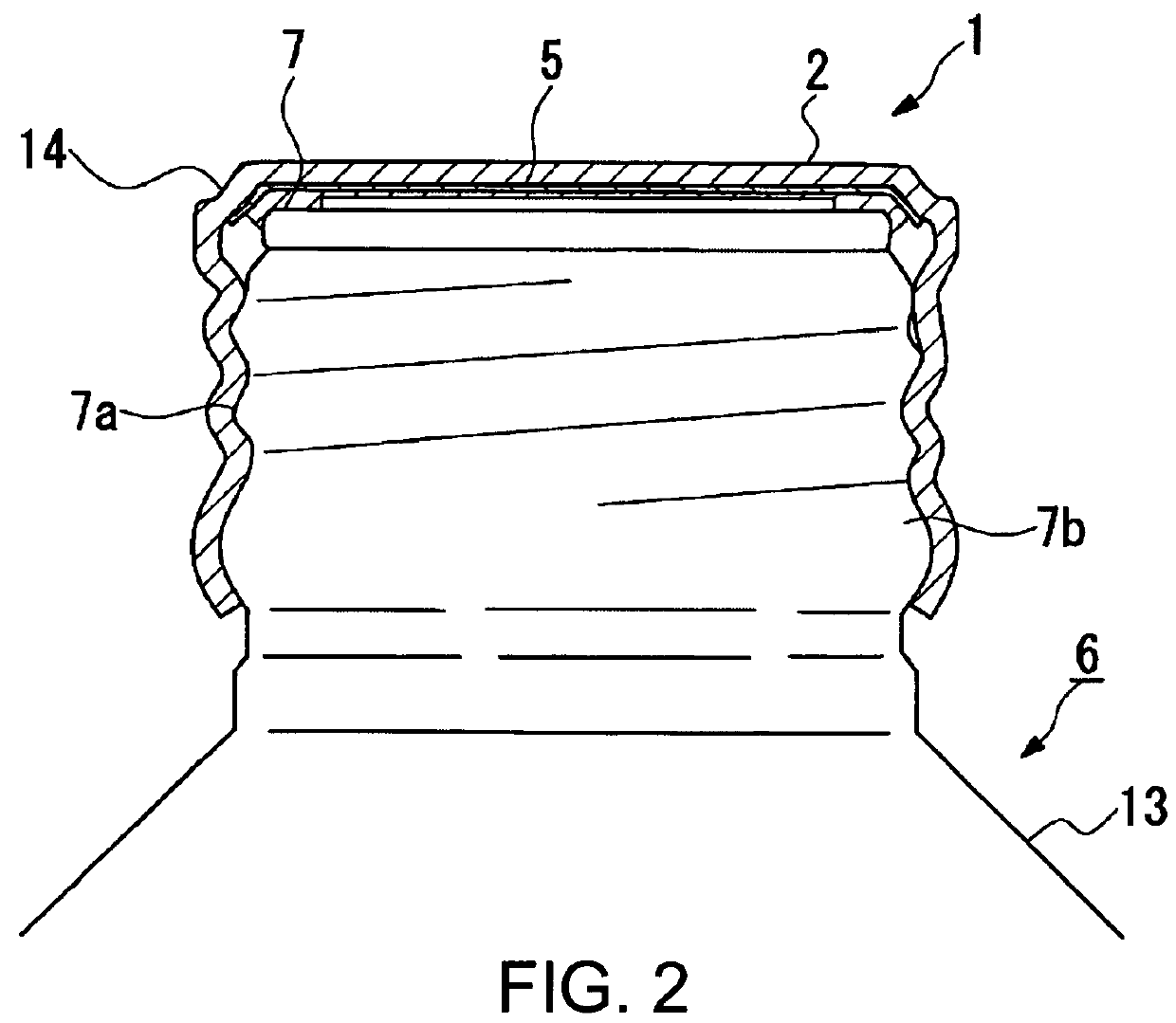
[0086]As shown in FIGS. 1 and 2, the cap 1 of the present embodiment includes a bottomed cylindrical metallic cap shell (cap body) 4 consisting of a top plate 2 and a tubular peripheral wall section 3 that hangs from peripheral edge of the top plate 2; and a tabular synthetic resin liner 5 provided not to fall off from the inner surface of the top plate. A cap-provided threaded container, for example, bottle (container) 6 of the present embodiment is provided with the cap 1 seamed to a mouthpiece (mouth) 7. Examples of the threaded container of the present invention include a bottle-like container, PET bottle, glass bottle, and the like.

[0087]The cap shell 4 is machined from a sheet made of, for example, aluminum or aluminum alloy, and the sheet used is a coated sheet of which the inner and outer surfac...

example 1

[0150]Next, the results of the comparative test carried out for confirming the effects of the present invention will now be described.

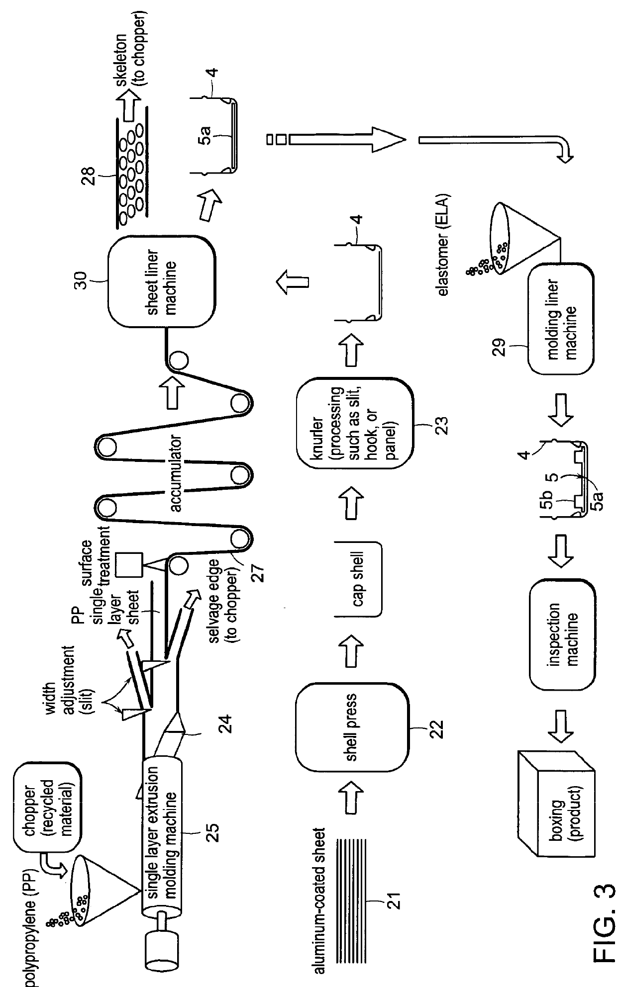
[0151]In this test, an aluminum alloy sheet with a thickness of 0.25 mm with its inner and outer surfaces painted was molded into a cap shell 4 for 38-mm PP cap (pilfer-proof cap). For the cap shell 4, an aluminum sheet of which the inner surface was baking-applied with a polyolefin lubricant-containing epoxy phenol coating material at the rate of 50 mg / dm2 was used. Then, a polypropylene sheet formed by an extruder 25 and T die 24 was punched into a 37.8 mm rigid sheet 5a, and the rigid sheet 5a was inserted into the cap shell 4 having an inner diameter φ of 38.05 mm. In the cap shell 4, the 12 liner locking hooks (liner stopping protrusion 9) protruding toward the interior with a length of 1.0 mm extending substantially horizontally along the top surface was formed. The position of the hook was 1.5 mm in height from the cap's top surface. An automat...

example 2

[0157]The liner of the present invention was produced as in Example 1, and compared with a conventional two-layer liner material as a Comparative Example. In the present invention, a sliding layer (rigid sheet) having a different outer diameter size was produced. After the insertion into a cap shell, a sealing layer (soft layer) was formed by the in-shell mold method. The size of the prototype sliding layer (rigid sheet) was estimated considering the upper limit and the lower limit of the present invention, and the prototype sliding layer was inserted into the cap shell. These were evaluated in the same manner as in Example 1. A conventional two-layer sheet was tested as a Comparative Example. The sheets of Comparative Examples were produced by extruding and laminating PP and styrene elastomer as in Example 1 from the two-layer extruder and the T die of a sheet molding machine, adjusting the thickness thereof by a cold roller, cutting them to a certain width. After cutting, the shee...


PUM


Abstract

Provided is a liner-provided cap for sealing the mouthpiece of a threaded container, which includes the cap shell 4 consisting of the top plate 2 and the tubular peripheral wall section 3 that hangs from the peripheral edge of the top plate 2, and the synthetic resin liner 5 provided on the inner surface of the top plate 2. The liner 5 includes the disk-shaped rigid sheet 5a disposed in contact with the inner surface of the top plate 2, and the soft layer 5b that is laminated to the rigid sheet 5a and is more flexible than the rigid sheet 5a. The soft layer 5b is concentric with the rigid sheet 5a and is formed in an annular or disk shape with a diameter smaller than that of the rigid sheet 5a so that the soft layer 5b can be brought into contact with at least the mouthpiece.

Description

BACKGROUND OF THE INVENTION[0001]1. Field of the Invention[0002]The present invention relates to a liner-provided cap and a cap-provided threaded container excellent in openability, sealing property, and suitability for liner setting.[0003]The present invention also relates to a liner-provided cap and a cap-provided threaded container excellent in openability, sealing property, and gas-barrier property.[0004]2. Description of the Related Art[0005]In general, a cap (container lid) used for such as a glass bottle, a PET bottle, and an aluminum bottle provided with a synthetic resin liner is in a wide use. In the case of a metallic cap, there are various methods for producing the same. Examples of such methods include a disk insertion method in which both sides of a sheet such as aluminum thin sheet, tin thin sheet, and chromium plating thin sheet (TFS: tin-free steel) are repeatedly coated several times, punched out, and molded into a cap shell (cap shell body) to thereby insert a pre...

Claims


Application Information

Patent Timeline
Patent Type & Authority Applications(United States)
IPC IPC(8): B65D41/04
CPCB65D41/045
Inventor HANAFUSA, TATSUYAMUTO, HIDEYASU
Owner UNIVERSAL CAN CORP
Why Eureka
Try Eureka