
Materials, components, and methods for use with extreme ultraviolet radiation in lithography and other applications

a technology of extreme ultraviolet radiation and materials, applied in the field of materials, components, and methods for using extreme ultraviolet radiation in lithography and other applications, can solve the problems of high electricity consumption, high manufacturing and imitation of such high-power light sources, and high cost of high-power euv light sources to build, so as to improve the reflectivity of elements and improve the transmission effect of elements

Active Publication Date: 2016-03-24
JAISWAL SUPRIYA
View PDF3 Cites 261 Cited by
  • Summary
  • Abstract
  • Description
  • Claims
  • Application Information

AI Technical Summary

Benefits of technology

The patent relates to an element that can be used in a light exposure system, which can improve the reflectivity and transmission of the element to greater than 70% for a selected wavelength. The element has plural structural features that can control or increase the electromagnetic radiation absorption for a selected wavelength. The material of the element can be deposited using atomic layer deposition, which can produce high quality films with low defectivity and surface roughness. The technical effects of this patent include improved light exposure and improved quality of the light exposure system.

Problems solved by technology

But the manufacture and imitation of such high power lightsource is highly undesirable.
High power EUV light sources are expensive to build, and have high electricity consumption.
Further, with substantially over 99% of the available energy being absorbed in the scanner, the optical components are susceptible to thermal damage and limited lifetime.
Most materials tend to absorb EUV radiation, consequently there are limited selection of materials available for optical elements used in photolithography systems.
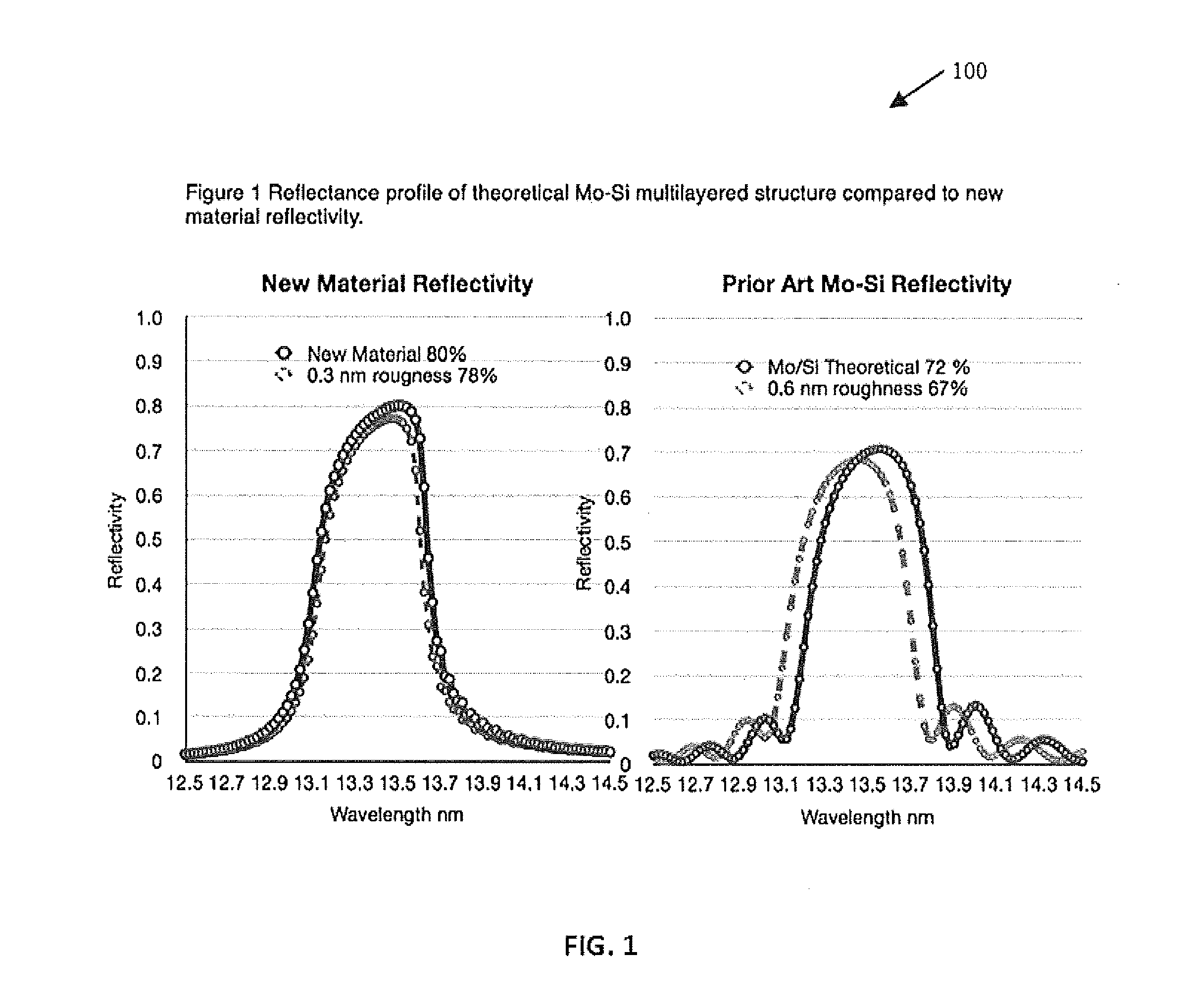
The fabrication of the multilayer is highly challenging and often theoretically predicted reflectivity values (72%) are not achieved in practice.
This limitation on reflectivity at each optical interface is primarily responsible for the poor overall energy efficiency of the scanner tool, and the light delivered to the wafer.

Method used


Image

  • Materials, components, and methods for use with extreme ultraviolet radiation in lithography and other applications
  • Materials, components, and methods for use with extreme ultraviolet radiation in lithography and other applications
  • Materials, components, and methods for use with extreme ultraviolet radiation in lithography and other applications

Examples


Embodiment Construction

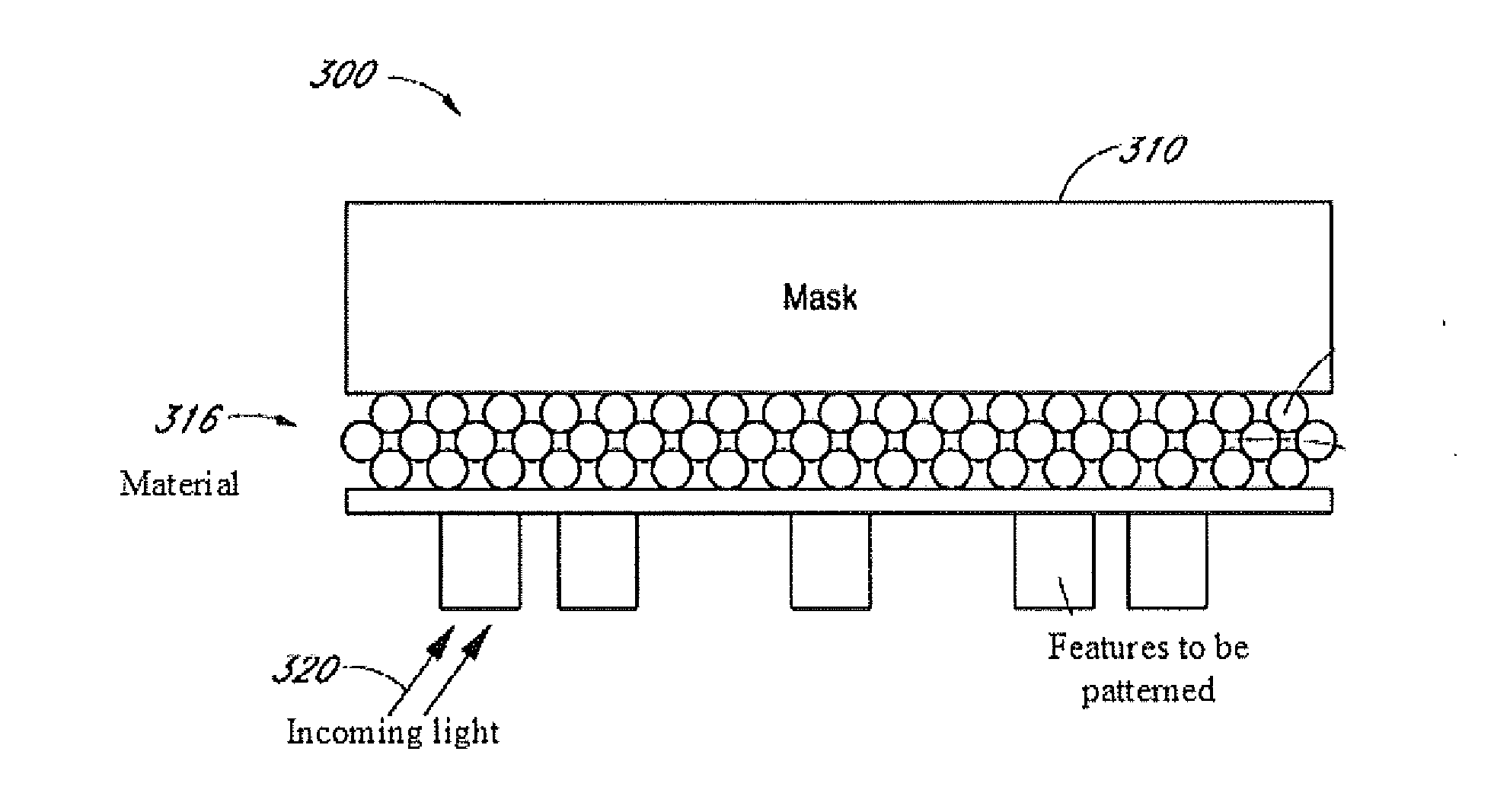
[0035]Lithography using extreme ultraviolet (EUV) radiation may enable fabrication of devices with smaller feature sizes. However, most materials have a high absorption for electromagnetic radiation in the EUV spectrum. The choice of natural materials with a low absorption rate in the EUV spectrum is limited. Accordingly, the high absorption of most materials affects the performance of EUV lithography (EUVL) systems. For example, high levels of optical power might be required to operate a EUVL system. The system might also require an extensive heat management system because of the increased optical power.

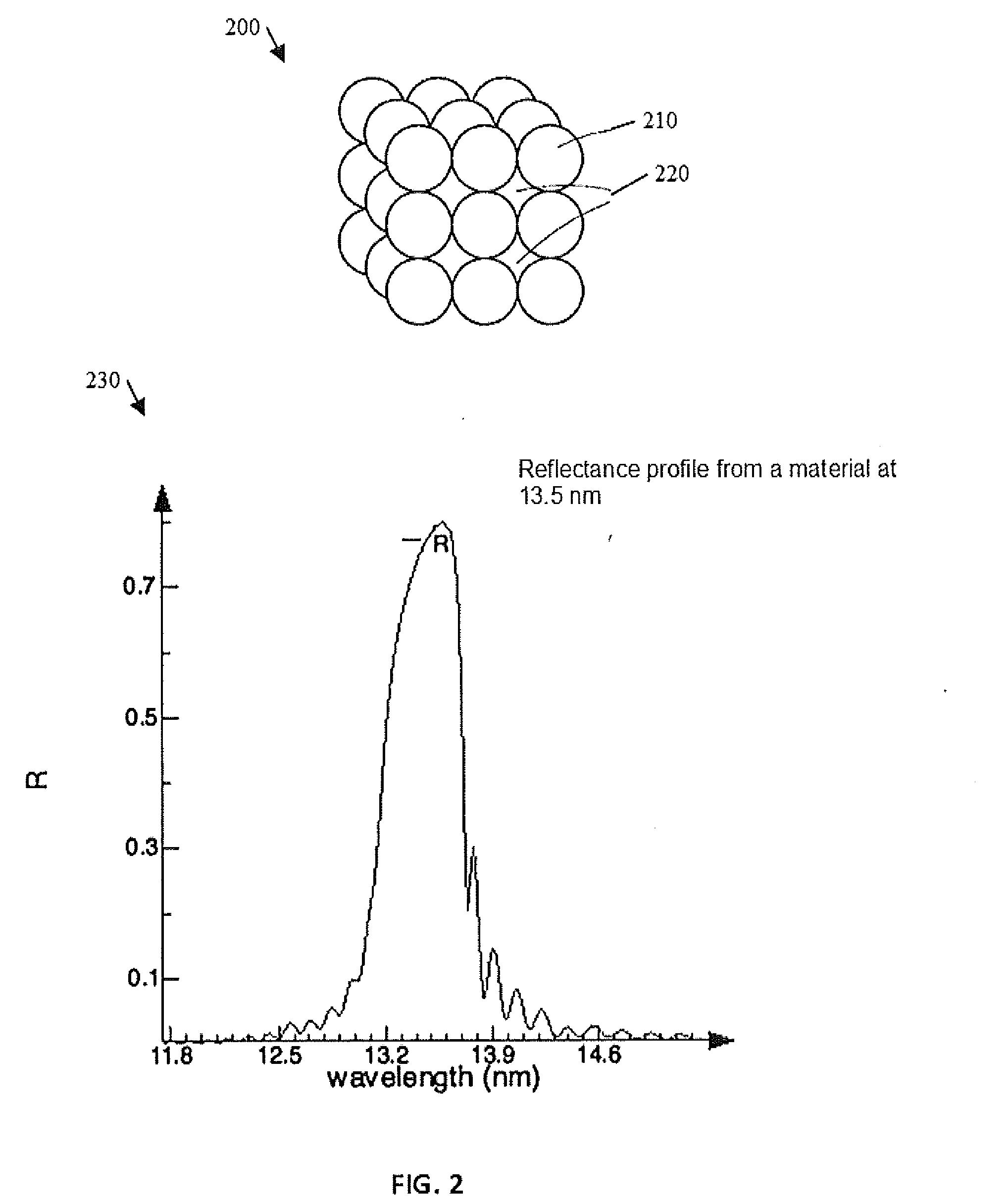
[0036]This disclosure describes materials or material configurations that can improve performance of EUVL systems. The disclosure further describes fabrication of these materials and using these materials in components, apparatus, and devices of a EUVL system. The materials, methods, and systems described here can also be used in systems where the electromagnetic radiation is in the...


PUM

PropertyMeasurementUnit
Efficiencyaaaaaaaaaa
Nanoscale particle sizeaaaaaaaaaa
Wavelengthaaaaaaaaaa

Abstract

Nanostructured photonic materials, and associated components for use in devices and systems operating at ultraviolet (UV), extreme ultraviolet (EUV), and / or soft Xray wavelengths are described. Such a material may be fabricated with nanoscale features tailored for a selected wavelength range, such as at particular UV, EUV, or soft Xray wavelengths or wavelength ranges. Such a material may be used to make components such as mirrors, lenses or other optics, panels, lightsources, masks, photoresists, or other components for use in applications such as lithography, wafer patterning, astronomical and space applications, biomedical applications, biotech or other applications.

Description

[0001]This application is a continuation in part of U.S. patent application Ser. No. 13 / 745,618, filed Jan. 18, 2013, entitled “Materials, Components, and Methods for Use with Extreme Ultraviolet Radiation in Lithography and Other Applications,” which is incorporated herein by reference, and is a non-provisional of U.S. Provisional Application No. 61 / 588,601, filed Jan. 19, 2012, titled “Materials, Components, and Methods for Use with Extreme Ultraviolet Radiation in Lithography & Other Applications,” the disclosure of which is hereby incorporated by reference in its entirety. This application also claims priority to U.S. provisional patent application No. 62 / 085,222, filed Nov. 26, 2014, which is incorporated herein in its entirety.BACKGROUND[0002]Over the past 50 years, the technological pace of advancement has been driven by the manufacture of integrated circuit chips. The complexity and density of integrated circuits has grown exponentially to achieve higher computing performanc...

Claims


Application Information

Patent Timeline
IPC IPC(8): G02B5/20C23C16/06C23C16/455G01Q60/24H01J37/28
CPCG02B5/208H01J37/28C23C16/06C23C16/45553G01Q60/24G02B1/005G02B5/085G02B5/0891G03F7/70958G03F1/24G03F1/52G03F7/70316G21K1/062
Inventor JAISWAL, SUPRIYA
Owner JAISWAL SUPRIYA
Learn More