
Coated separators for lithium batteries and related methods

a technology of coated separators and lithium batteries, applied in the manufacture of final products, batteries, cell components, etc., can solve the problems of unwanted emissions, volatile non-aqueous solvents used to dissolve pvdf, and adverse effects on battery performance, etc., to achieve the effect of reducing shrinkage, improving thermal stability, and reducing porosity

Pending Publication Date: 2016-06-09
CELGARD LLC
View PDF7 Cites 57 Cited by
  • Summary
  • Abstract
  • Description
  • Claims
  • Application Information

AI Technical Summary

Benefits of technology

The patent describes a new type of separator for lithium ion batteries that has improved safety and performance. The separator is coated with a mixture of particles and aqueous or water-based polymeric binders. The coating layer helps prevent oxidation reactions and shorts, and it also provides thermal stability and extends the battery's shutdown performance. The ceramic coating also improves the adhesion between the separator and the battery's electrodes. Overall, this new separator improves the safety and performance of lithium ion batteries.

Problems solved by technology

Good contact between separator and electrodes may be important for optimal cycle life in a lithium battery, as the presence of voids or spaces between a separator and the electrodes may have an adverse effect on long term cycle life or battery performance.
However, the non-aqueous solvents used to dissolve PVDF often are volatile and may require careful use, disposal and / or recycling, as they may not be environmentally friendly and may produce unwanted emissions if not handled properly.
Coating processes based on non-aqueous systems can be costly, may have an unfavorable environmental footprint, and may be difficult to handle due to safety concerns related to their flammability.

Method used


Image

  • Coated separators for lithium batteries and related methods
  • Coated separators for lithium batteries and related methods
  • Coated separators for lithium batteries and related methods

Examples


example 1

[0077]An aqueous-based PVDF / ceramic coating slurry was prepared by uniformly dispersing 25 grams of high purity alumina particles having a D50 average particle diameter of 0.65 μm, a bulk tapped density of 0.8 g / cm3 and a BET surface area of 4.6 m2 / g with 18.7 grams of Formulation #1, a 50:50 blend of Formulation #2 and Formulation #3, two aqueous solutions or suspensions of PVDF:HFP (available from Arkema Inc. of King of Prussia, Pa., under the product line Kynar® Latex) which differ by content of HFP and are described in more detail below. Improved mixing was achieved by first pre-wetting the alumina particles with the Formulation #1 solution or suspension. Dispersion was accomplished using a Silverson High Shear L4M-5 mixer at 5000 rpm for 12 minutes at room temperature. The slurry was applied to the surface of a Celgard®2400 PP microporous membrane (a membrane made by a dry process, also known as the Celgard® process and having a thickness of about 25 μm, a porosity of about 41%...

example 2

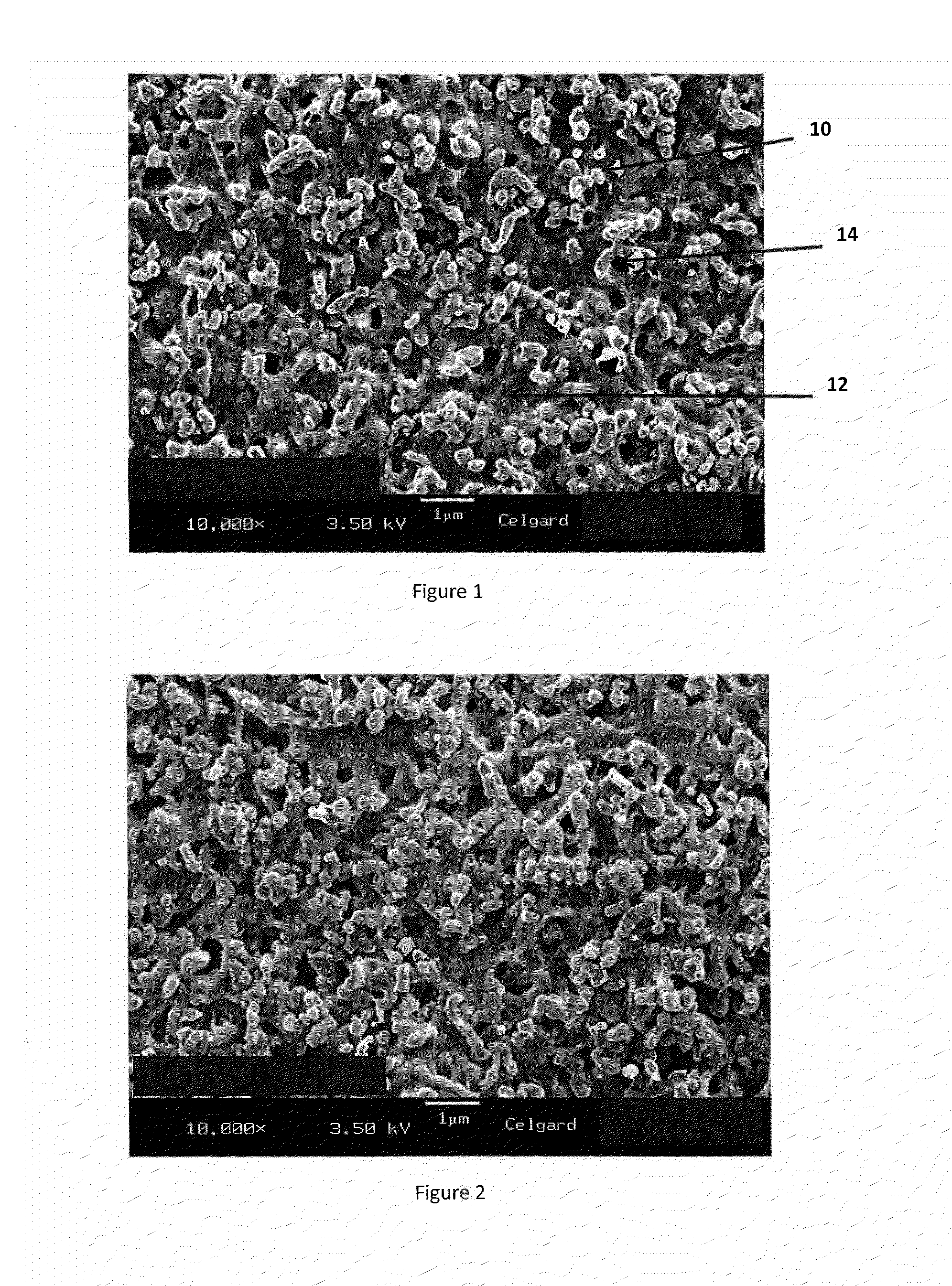
[0080]An aqueous-based PVDF / ceramic coating slurry was prepared by dispersing 39 grams of high purity alumina particles having a D50 average particle diameter of 0.65 μm, a bulk tapped density of 0.8 g / cm3 and a BET surface area of 4.6 m2 / g with 16.8 grams of the PVDF Formulation #1 blend described in Example 1 above. Improved mixing was achieved by first pre-wetting the alumina particles with the Formulation #1 solution or suspension. Dispersion was accomplished using a Silverson High Shear L4M-5 mixer at 5000 rpm for 12 minutes at room temperature and then using a Ball mill mixer (MTI Shimmy Ball Mixer) for 20 minutes. The ceramic / PVDF slurry was hand coated on a surface of a Celgard®2400 PP microporous membrane (the features of which membrane are described in Example 1 above) using a doctor blade, and the water was removed by oven drying at 79° C. An SEM of the surface of this coated separator membrane, taken at 10,000× magnification, is shown in FIG. 2. Components of the coating...

example 3

[0081]An aqueous-based PVDF / ceramic coating slurry was prepared by mixing and uniformly dispersing 66 grams of high purity alumina particles having a D50 average particle diameter of 0.65 μm, a bulk tapped density of 0.8 g / cm3 and a BET surface area of 4.6 m2 / g with 23.5 grams of Formulation #2, a Kynar® Latex product available from Arkema and generally described as an aqueous suspension of water (55-65%) and PVDF:HFP, which PVDF:HFP has a melt temperature in the range of about 114-120° C. Improved mixing was achieved by first pre-wetting the alumina particles with the Formulation #2 solution or suspension. Dispersion was accomplished using a Silverson High Shear L4M-5 mixer at 3000 rpm for 5 minutes at room temperature followed by mixing in Ball mill mixer (MTI Shimmy Ball Mixer) for 20 minutes. The slurry was hand coated onto the surface of a Celgard®EK0940 polyethylene microporous membrane (a membrane made from a wet process and having a thickness of about 9 μm, a porosity of abo...


PUM

PropertyMeasurementUnit
diameteraaaaaaaaaa
thicknessaaaaaaaaaa
temperatureaaaaaaaaaa

Abstract

In accordance with at least selected embodiments, new or improved ceramic coated separators, membranes, films, or the like for use in lithium batteries, new or improved batteries including such ceramic coated separators, membranes, films, or the like, and methods of making or using such ceramic coated separators, membranes, films or the like are disclosed. In accordance with at least certain embodiments, new or improved aqueous or water-based polymeric coated separators, membranes, films, or the like are disclosed. In accordance with at least particular embodiments, new or improved aqueous or water-based polyvinylidene fluoride (PVDF) or polyvinylidene difluoride (PVDF) homopolymer or co-polymers of PVDF with hexafluoropropylene (HFP or [—CF(CF3)—CF2—]), chlorotrifluoroethylene (CTFE), vinylidene fluoride (VF2.HFP), tetrafluoroethylene (TFE), and / or the like, blends and / or mixtures thereof, coated separators, membranes, films or the like, new or improved porous separators for use in lithium batteries, new or improved coating or application methods for applying a coating or ceramic coating to a separator for use in a lithium battery, new or improved PVDF or PVDF:HFP films or membranes, and / or the like are disclosed.

Description

CROSS-REFERENCE TO RELATED APPLICATIONS[0001]This application claims priority to and the benefit of co-pending U.S. Provisional Patent Application Ser. No. 62 / 087,953, filed Dec. 5, 2014, which is incorporated herein by reference in its entirety.FIELD OF THE INVENTION[0002]Various new, optimized or improved coated separators, membranes, films, or the like for use in lithium batteries, such as lithium ion batteries or lithium ion polymer batteries, new or improved batteries including such coated separators, membranes, films, or the like, and methods of making or using such coated separators, membranes, films or the like are disclosed herein. In accordance with at least selected embodiments, aspects or objects, new, optimized and / or improved ceramic coated separators, membranes, films, or the like for use in lithium batteries, such as lithium ion batteries or lithium ion polymer batteries, new or improved batteries including such ceramic coated separators, membranes, films, or the lik...

Claims


Application Information

Patent Timeline
Patent Type & Authority Applications(United States)
IPC IPC(8): H01M2/16H01M2/14H01M10/0525H01M50/403H01M50/414H01M50/434H01M50/449H01M50/457H01M50/489
CPCH01M2/1686H01M10/0525H01M2220/20H01M2/1606H01M2/145H01M50/44H01M50/403H01M50/449H01M50/489H01M50/414H01M50/434H01M50/457Y02E60/10Y02P70/50H01M50/417H01M50/426H01M50/446H01M50/409H01M50/4295H01M10/052H01M50/451H01M50/454H01M50/443
Inventor ZHANG, ZHENGMINGHE, JINBOLI, XUEFAJEON, INSIKSHI, LIEWATSON, JILL V.
Owner CELGARD LLC
Learn More