Methods and systems for coherent raman scattering

a coherent and raman scattering technology, applied in the field of coherent raman scattering methods and systems, can solve the problems of weak spontaneous raman scattering signal, impracticality of current spontaneous raman scattering system for cell sorting, long averaging time, etc., and achieve the effect of reducing the background signal and reducing the laser cavity repetition ra

Inactive Publication Date: 2016-06-23
INVENIO IMAGING
View PDF7 Cites 60 Cited by
  • Summary
  • Abstract
  • Description
  • Claims
  • Application Information

AI Technical Summary

Benefits of technology

[0009]In various aspects, the systems and methods of the invention include additional features. In some embodiments, laser duty factors for the first and the second train of pulses are larger than 10,000 and at least one of Δω1 and Δω2 is smaller than 50 cm−1. In some embodiments, the non-linear optical signal comprises Coherent Raman Scattering (CRS), wherein the difference in frequency of a first spectral component within Δω1 and a second spectral component within Δω2 is resonant with a targeted vibrational frequency of a sample. In some embodiments, the CRS comprises Coherent anti-Stokes Scattering (CARS) and the detector system is further configured to detect radiation at the corresponding anti-Stokes wavelength. In some embodiments, the CRS comprises Stimulated Raman Scattering (SRS) and the detector system is further configured to detect an intensity gain or loss at a wavelength within Δω1 or Δω2. In some embodiments, the CRS comprises Raman Induced Kerr Effect (RIKE) and the detector system is further configured to detect a polarization rotation at a wavelength within Δω1 or Δω2. In some embodiments, Δω1 and Δω2 are smaller than 50 cm−1. In some embodiments, at least one of ω1 and ω2 is tunable. In some embodiments, Δω1 is smaller than 50 cm−1 and Δω2 is larger than 50 cm−1. In some embodiments, the detector system comprises a detector array that is configured to detect signals from a plurality of vibration frequencies in the at least one overlapping focal volume. In some embodiments, the ratio of the duration of pulses in the first and the second train of pulses is between 1-3. In some embodiments, the second train of pulses is synchronized with the first train of pulses using optical synchronization, electronic feedback or feed forward synchronization. In some embodiments, the first or the second trains of pulses is frequency shifted using a broadband supercontinuum (SC). In some embodiments, the first or second train of pulses is amplified in a gain medium. In some embodiments, the gain medium comprises an Erbium (Er)-, Ytterbium (Yb)-, Thulium (Tm)-, Holmium (Ho)-, or Neodymium (Nd)-doped medium. In some embodiments, systems or methods of the invention further comprise an undoped fiber in a laser cavity of the laser fiber optics system such that the laser repetition rate of the laser cavity is reduced. In some embodiments, the system is configured to broaden the first or the second train of pulses using self-phase modulation (SPM). In some embodiments, systems and methods of the invention further comprise a flow system configured to generate a stream of particles through the at least one overlapping focal volume. In some embodiments, the particles comprise cells. In some embodiments, methods and systems of the invention comprise a high-speed signal processor that is capable of performing spectral analysis. In some embodiments, methods and systems of the invention comprise a sorting device that is configured to sort a particle with the stream of particles according to an output from the high-speed signal processor. In some embodiments, the dimension of the at least one overlapping focal volume along the direction of the stream of particles is less than the dimensions that are perpendicular to the direction of the stream of particles. In some embodiments, the detection system further comprises a scanner that is configured to spatially scan the at least one overlapping focal volume over a field of view larger than 500 μm. In some embodiments, the focusing optics comprise a fiber-optic probe. In some embodiments, methods and systems of the invention comprise at least one of a ball-lens, a GRIN lens, or a micro-optic lens that is configured to focus a beam comprising the first or second train of pulses toward the at least one overlapping focal volume. In some embodiments, the fiber-optic probe further comprises a section of core-less or multi-mode fiber that is configured to expand the beam comprising the first or second trains of pulses before the at least one of a ball-lens, GRIN lens or micro-optic lens. In some embodiments, the fiber-optic probe further comprises a dual-clad fiber that is configured to deliver the first or the second trains of pulses through a fiber core and wherein the fiber-optic probe is configured to couple the non-linear optical signal into an inner cladding for delivery to the detector. In some embodiments, the fiber-optic probe further comprises a section of core-less or multi-mode fiber for expanding the beam comprising the first or second trains of pulses before the at least one of a ball-lens, GRIN lens or micro-optic lens, and wherein the section of multi-mode fiber couples to the inner cladding of the dual-clad fiber. In some embodiments, methods and systems of the invention further comprise a color filter in the fiber-optic probe, wherein the color filter is configured to reduce a background signal from the delivery fiber.

Problems solved by technology

However, the spontaneous Raman scattering signal is weak and long averaging times are required to obtain high signal-to-noise ratio (SNR) spectra.
Current examples in biofuel research involve laser trapping a cell for 10 seconds to generate enough signal, thereby making current spontaneous Raman scattering systems for cell sorting impractical.

Method used


Image

  • Methods and systems for coherent raman scattering
  • Methods and systems for coherent raman scattering
  • Methods and systems for coherent raman scattering

Examples


example 1

A CRS Flow Cytometer

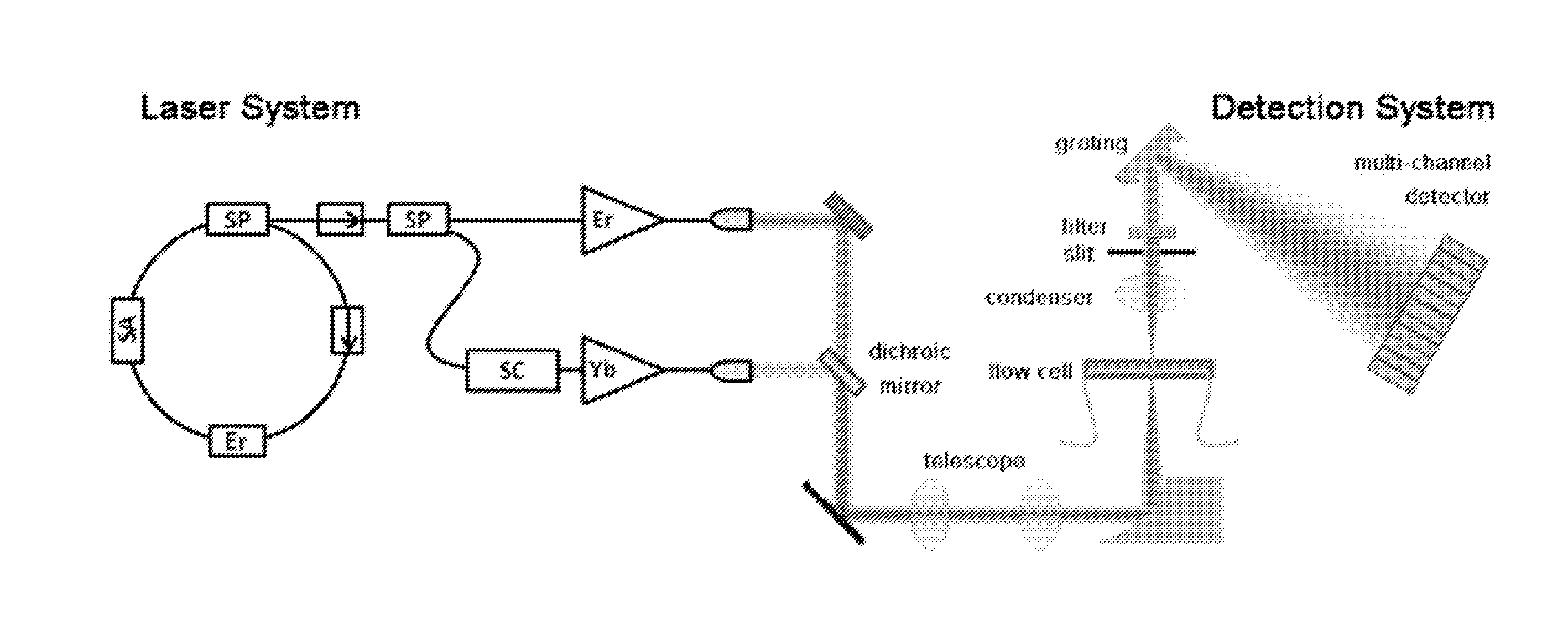
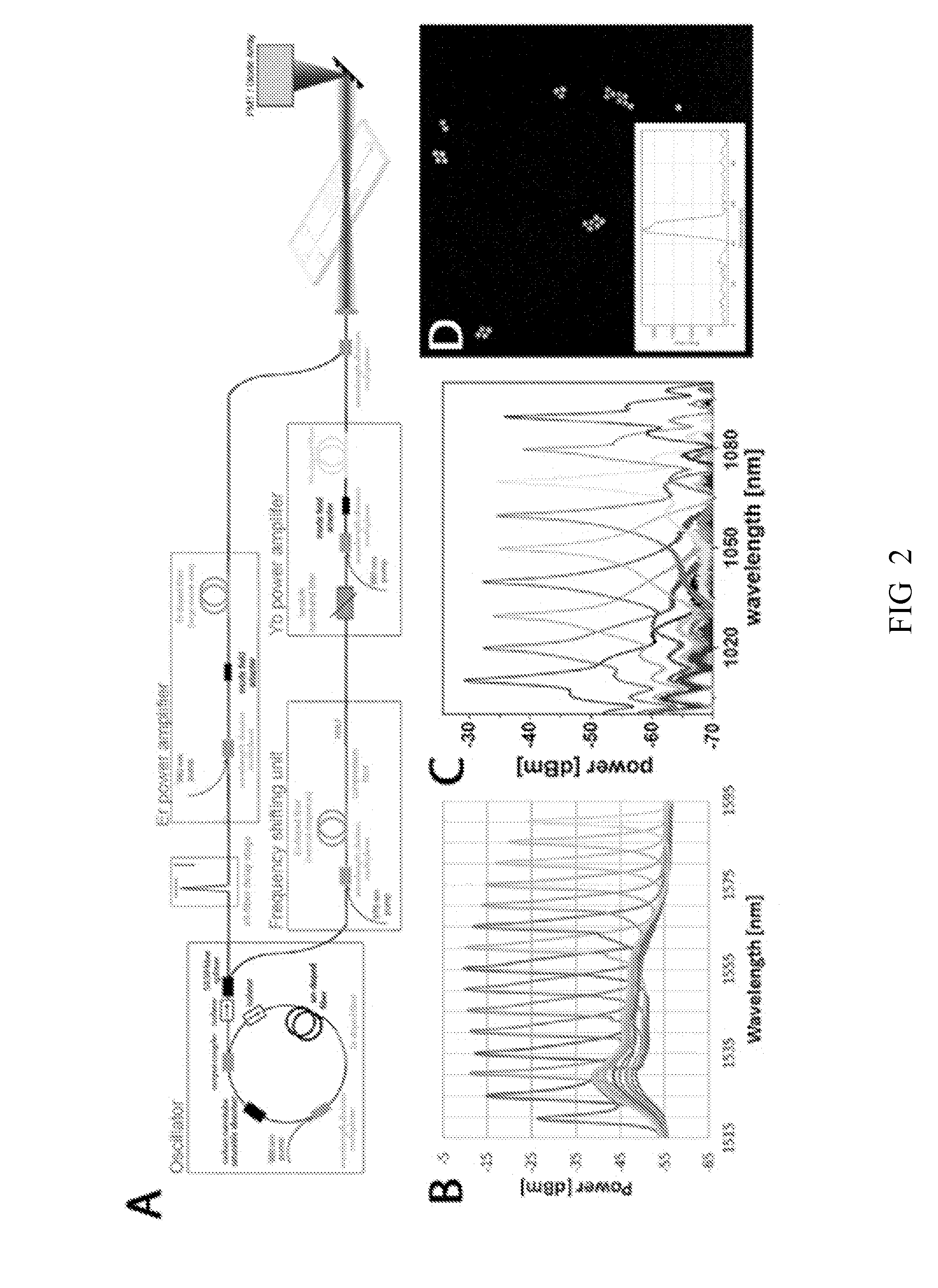
[0169]This example includes building and characterizing the laser source for the high-throughput CRS-based cell sorter, building the detection system, and demonstrating the performance of the complete system which includes the laser source, CRS-based cell sorter and the detection system. This example includes an all-fiber laser source for a high throughput multiplexed CRS flow cytometer. A dual-wavelength laser platform (e.g., FIG. 2A) can be used for optical synchronization of Er- and Yb-doped power amplifiers, which may have a difference in center wavelengths that might allow access to the high wavenumber region (2750 cm−1 to 3400 cm−1) of Raman spectra where most of CRS can be performed. Accessing the fingerprint region of Raman spectra may also be possible (e.g., by utilizing Thulium (Tm) and Holmium (Ho) co-doped amplifiers).

[0170]The laser illumination system (1) and the detection system (2) can be arranged for CRS applications. For the flow system (2), cus...

example 2

CRS Flow Cytometry—Spectral Calibration

[0186]This example describes a protocol for spectral calibration for systems and methods of the present invention. For example, the calibration protocol can be used for calibrating a CRS flow cytometer system described herein. Example calibration protocols are described below.

[0187]FIGS. 6A & 6B show the spectra of the excitation lasers for multiplex CRS. In some aspects of the present invention, the bandwidth of the Stokes beam can be generated by spectral broadening of a femtosecond input beam due to SPM during amplification. SPM may result in a non-uniform spectral coverage (IStokes(λ)≠const.). A strong signal in the wings can be desirable as the SPM-broadened output is usually chirped (e.g., different wavelengths are present in the focus at different times). The narrowband beam can be unchirped and can be close to Gaussian. To maximize the signal and minimize sample damage, it may be desirable to match the pulse duration of the two excitati...

example 3

CRS Flow Cytometry—Prototype System & Results

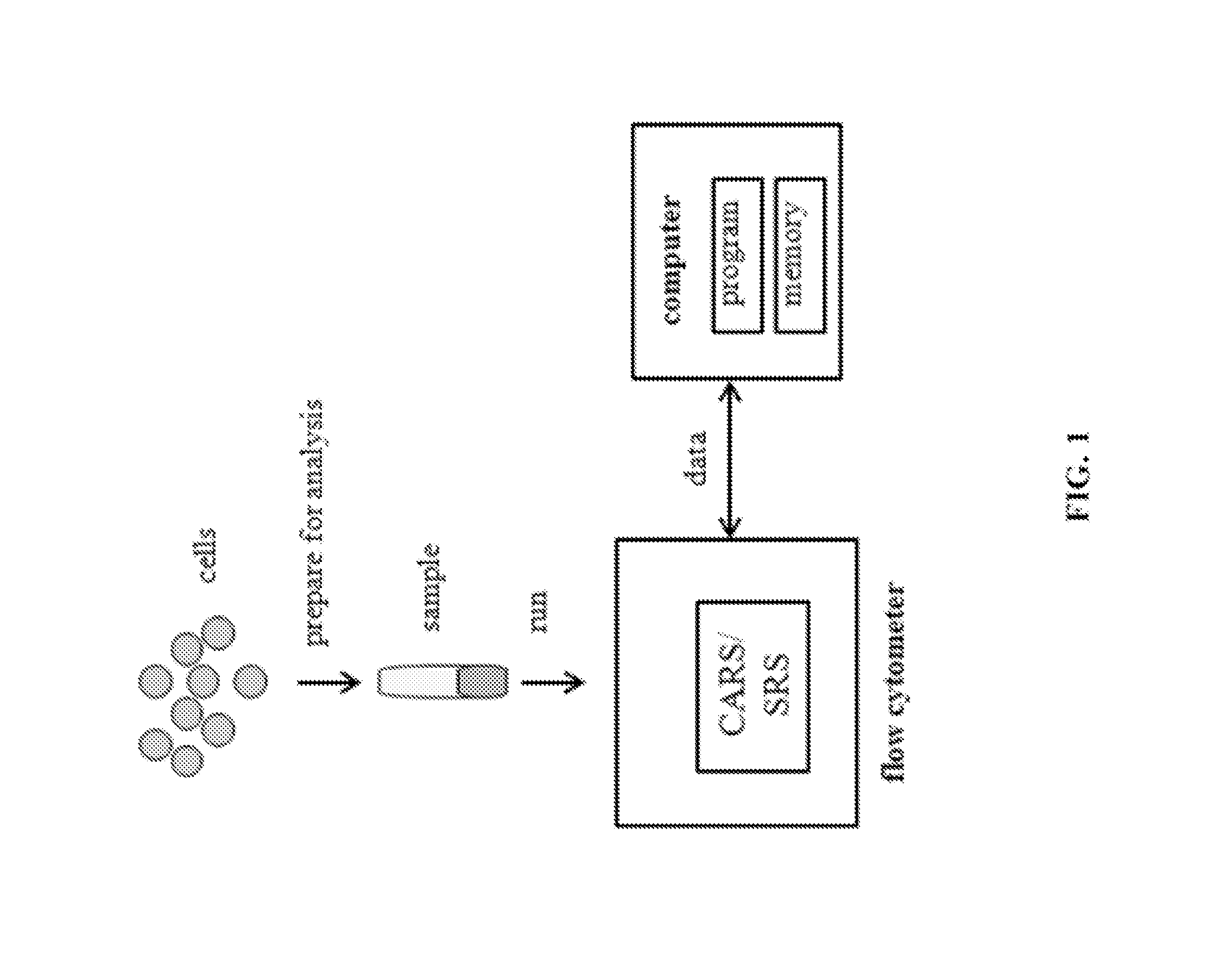
[0195]A prototype system was designed and developed to demonstrate proof-of-concept for a high-speed Raman spectroscopy platform based on multiplex CRS. While spontaneous Raman scattering is highly specific and allows for single-cell measurements, the major disadvantage is that the signal is extremely weak and long averaging times are required to obtain high signal-to-noise ratio (SNR) spectra (e.g., 10 seconds per cell). This renders a spontaneous Raman scattering-based flow cytometer or cell sorter impractical. In CRS, the sample is excited with two laser beams with a difference frequency tuned to match a particular vibration of the sample. Such coherent excitation of a targeted vibration results in a large increase in signal, by >10,000× compared spontaneous Raman scattering.

[0196]Most implementations of CRS microscopy have been based on narrowband CRS using two narrowband lasers to target a particular Raman vibration; different Raman ...


PUM


Abstract

Systems and methods employing Coherent Raman Scattering (CRS), e.g., Coherent anti-Stokes Raman Spectroscopy (CARS) and/or Stimulated Raman Scattering (SRS) are provided. Systems and methods for performing flow cytometry, imaging and sensing using low-resolution CRS are also provided.

Description

RELATED APPLICATIONS[0001]This application claims the benefit of U.S. Provisional Application Nos. 61 / 836,077, filed Jun. 17, 2013, 61 / 838,109, filed Jun. 21, 2013, 61 / 908,548, filed Nov. 25, 2013, and 61 / 908,669, filed Nov. 25, 2013, which are herein incorporated by reference in their entirety.STATEMENT AS TO FEDERALLY SPONSORED RESEARCH[0002]This invention was made with the support of the United States government under SBIR grant number IIP-1248414 from the National Science Foundation. The government may have rights in the invention.BACKGROUND OF THE INVENTION[0003]The Raman process involves the scattering of an excitation photon by a molecule while exciting a molecular vibration. Each type of bond has a specific stiffness (e.g., C═C is stiffer than C—C) and associated mass (e.g., C—C is heavier than C—H) and thus a specific vibrational frequency. The dispersed Raman scattering spectrum is determined by the molecular vibrations of the sample and thus derived from the chemical comp...

Claims


Application Information

Patent Timeline
Patent Type & Authority Applications(United States)
IPC IPC(8): G01J3/44G01J3/02
CPCG01J3/4412G01J3/0208G01J3/0218G01J3/44G01N15/1434G01N15/1459G01N21/65G01N2015/1006G01N2015/1447G01N2021/653G01N2021/655
Inventor FREUDIGER, CHRISTIAN WILHELMTRAUTMAN, JAY KENNETH
Owner INVENIO IMAGING
Why Eureka
Try Eureka