Method for continuous production of aligned nanostructures on a running substrate and related device

a technology of aligned nanostructures and running substrates, which is applied in the direction of aligned nanotubes, organic compounds/hydrides/coordination complexes, physical/chemical process catalysts, etc., can solve the problems of limited cvd method by pre-deposition, large complexity of the steps sequence, and limited catalyst life. achieve the effect of improving the chemical compatibility of nanostructures

Inactive Publication Date: 2016-10-06
COMMISSARIAT A LENERGIE ATOMIQUE ET AUX ENERGIES ALTERNATIVES
View PDF4 Cites 17 Cited by
  • Summary
  • Abstract
  • Description
  • Claims
  • Application Information

AI Technical Summary

Benefits of technology

[0031]According to one preferred embodiment of this first alternative in which the catalytic precursor is ferrocene and the source precursor is toluene, the concentration of ferrocene present in the catalytic precursor and source precursor mixture (ferrocene and toluene mixture) is between 0.05% and 0.5% by weight. In this range of values, the inventors have observed that the catalytic synthesis yield and the growth speed of the nanostructures dramatically increase, thus dramatically decreasing the iron content (and increasing the purity of the nanostructures). Preferentially, the concentration of ferrocene is between 0.1% and 0.25% by weight, in which range the catalytic yield and the growth speed achieved are the highest, which has a significant advantage in terms of production and purity of the carbon nanostructures.
[0070]Further, as seen above, the modification of the operating conditions during the synthesis, in particular the decrease in the concentration of the catalytic precursor up to very low values (typically 0.01% by weight), allows for dramatically changing the purity of the carbon nanostructures, the overall yield and / or the growth speed. Finally, the choice between the first, second and third alternatives of the method according to the invention is made the following way:

Problems solved by technology

In comparison, the CVD method by pre-deposition is restricted by the lifetime of the catalyst which, in the case of carbon nanotubes, is poisoned by the carbon of the carbon precursor if no adjuvant is added to the carbon source.
However, the complexity of the sequence of the steps is very great, with for example treatment phases of the pre-deposition, which will strongly slow down the running speed of the support and thus decrease the productivity and increase the cost of nanostructures thus made on this support.

Method used


Image

  • Method for continuous production of aligned nanostructures on a running substrate and related device
  • Method for continuous production of aligned nanostructures on a running substrate and related device
  • Method for continuous production of aligned nanostructures on a running substrate and related device

Examples


examples 1a , 1b and 1c

Examples 1a, 1b and 1c

Making and Characterising a Dense Carpet of Aligned Carbon Nanotubes, Obtained According to a Synthesis Protocol Based on One or More Time Sequences (Stationary Substrate)

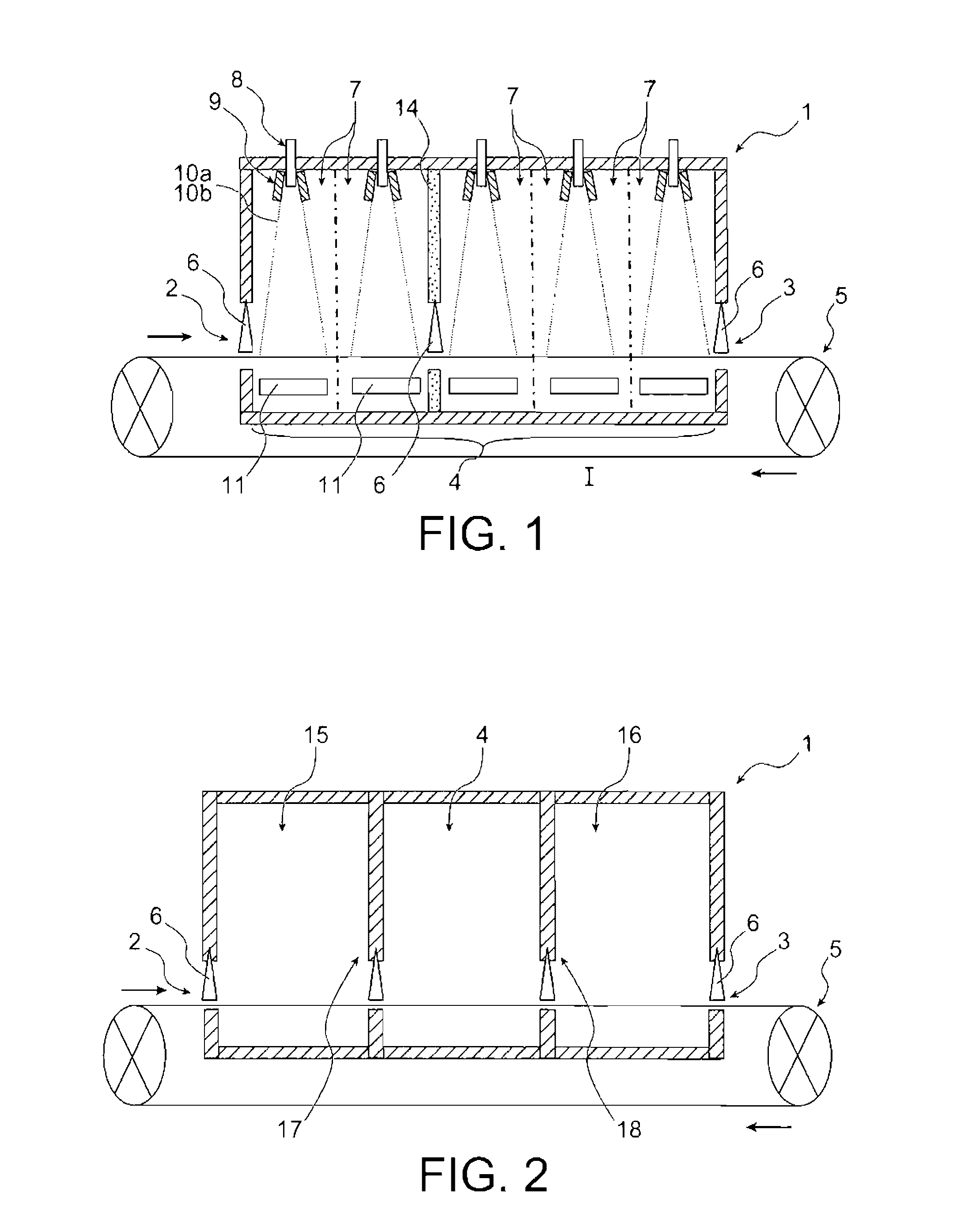
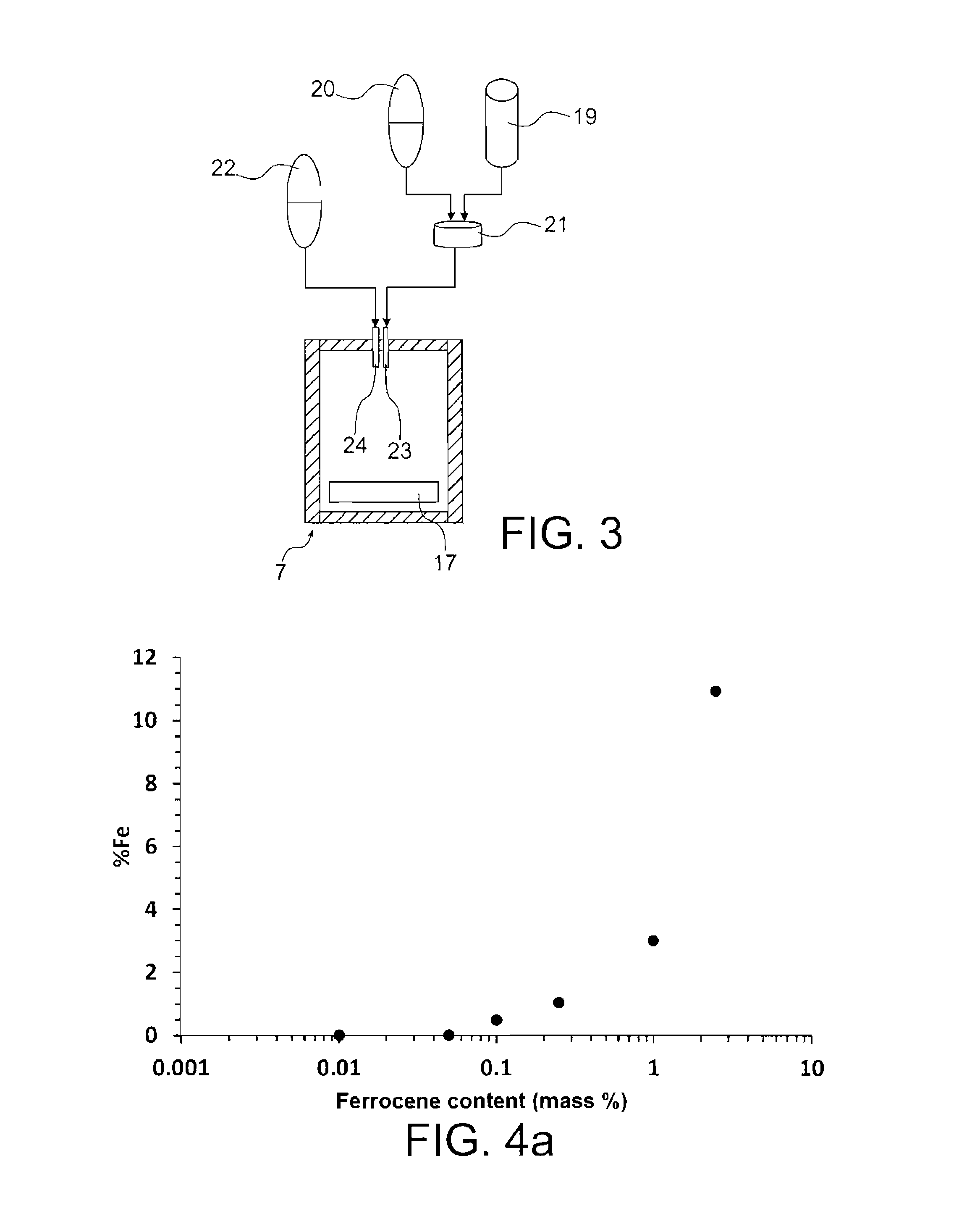
[0123]In this example, a CVD enclosure is used, the reaction chamber of which is a horizontally provided quartz tube in which a stationary substrate is positioned before growing the nanostructures (typically a laboratory device as described in document [7]).

[0124]The precursor (catalytic+source) mixture required for growing the nanostructures is sequentially injected over time, each of the sequences being characterised by a different concentration of the catalytic precursor in the case when there are at least two sequences.

[0125]Examples 1a, 1 and 1c below will enable characteristics both about synthesis (yields) and nanotubes thus obtained (purity, growth speed, diameters, etc.) to be measured and optimum ranges of synthesis parameters to be determined.

example 1a

Injection of a Constant Concentration of Ferrocene During One Single Sequence

[0126]FIGS. 4a to 9b show the results obtained by continuously injecting in a single sequence a constant concentration of ferrocene in the toluene / ferrocene mixture with, in particular, the effect of different concentrations of ferrocene (between 0.01 and 2.5% by weight for the different syntheses, with respectively 0.01, 0.05, 0.1, 0.25, 1, 2.5% by weight for samples 1 to 6) on the characteristics of the method and the nanotubes obtained.

[0127]The nanotubes are synthesised at a temperature of 800° C. by using an argon / H2 mixture (70 / 30% vol) as a carrier gas, for a time period of 15 minutes.

[0128]FIGS. 4a, 4b and 4c respectively represent the variations in the residual iron content in the samples (FIG. 4a), catalytic yield (FIG. 4b) and growth speed (FIG. 4c) as a function of the concentration of ferrocene implemented.

[0129]The iron content is measured by thermogravimetric analysis (TGA) under the air: the...

example 1b

Injection of a Constant Concentration of Ferrocene During One Single Sequence in the Presence of a Reactive Fluid (Acetylene)

[0142]FIGS. 10a-b and 11a-b show the results obtained by continuously injecting in a single sequence a constant concentration of ferrocene in the toluene / ferrocene mixture (10% by weight) with, in particular, the effect of the reactive fluid (acetylene) on the characteristics of the method and the nanotubes obtained.

[0143]The nanotubes are synthesised at a temperature of 800° C. by using a gaseous mixture Ar / H2 / C2H2 (0.70 / 0.30 / 0.03 L·min−1) with Ar as a carrier gas and H2 / C2H2 as a reactive fluid, for a time period of 15 minutes.

[0144]FIG. 10a illustrates the morphology of the nanotubes observed by SEM scanning electron microscopy) at the surface of the quartz support. It is observed that carbon nanotubes obtained are aligned, long, and contain a very small amount of impurities (residual catalyst (iron)-based particles), disorganised carbon particles).

[0145]Th...


PUM

PropertyMeasurementUnit
diameteraaaaaaaaaa
temperatureaaaaaaaaaa

Abstract

The invention relates to a method for continuously manufacturing aligned nanostructures on a running support, which comprises conveying the support through a heated space and synthesising, in this space, aligned nanostructures on the support by catalytic chemical vapour deposition. The heated space is divided into n consecutive zones in the conveying direction of the support (n being an integer ≧2), and the synthesis of the nanostructures results from heating and injection operations, in each of these n zones, of a flux of an aerosol containing a catalytic precursor and a source precursor of the material of the nanostructures to be formed, carried by a carrier gas. The injection operations are made by modifying, in at least two of the n zones, at least one parameter chosen among the flow rate of the carrier gas flux, the chemical composition of the carrier gas, the mass concentration of the catalytic precursor in the catalytic precursor and source precursor mixture. The invention also relates to a device for implementing this method.

Description

TECHNICAL FIELD[0001]The present invention relates to continuously manufacturing aligned nanostructures on a running host material, the nanostructures possibly being for example nanotubes or nanowires and the host material possibly being a substrate, a fibre or any other support.[0002]More particularly, the invention relates to a method dedicated to continuously manufacturing aligned nanostructures on a support by catalytic chemical vapour deposition and its related device.[0003]The method and device according to the invention have numerous possible applications. They can for example be used for making aligned nanotubes. Advantageously, the method enables carbon-based aligned nanotubes to be made with or without inserting heteroatoms (heteroatoms being for example phosphorus, boron, or nitrogen). Other tubular structures can also be contemplated as, for example and in a non-exhaustive way, nanowires of boron nitride, titanium dioxide, silicene or else. In the same way, the method an...

Claims


Application Information

Patent Timeline
Patent Type & Authority Applications(United States)
IPC IPC(8): C23C16/455B01J31/22C01B31/02
CPCC23C16/455C01B31/0233B01J31/2295C01B2202/08Y10S977/843B01J2531/842B82Y40/00B82Y30/00Y10S977/742B01J2231/005B01J19/22B01J2219/00159B01J2219/00186B01J19/1862B01J4/002C01B32/162C01B32/164
Inventor BOULANGER, PASCALMAYNE, MARTINEPINAULT, MATHIEUCHARON, EMELINEREYNAUD, CECILE
Owner COMMISSARIAT A LENERGIE ATOMIQUE ET AUX ENERGIES ALTERNATIVES
Why Eureka
Try Eureka