Density enhancement methods and compositions

a density enhancement and composition technology, applied in the field of density enhancement methods and compositions, can solve the problems of large problem of not being able to achieve general tractability of granular composite design based on constituent geometry and characteristics, and the strength of finished armor is not only difficult to fabricate but also stronger, so as to achieve more reproducible manufacturing, improve thermal conductivity, and reduce porosity

Active Publication Date: 2016-12-22
THE TRUSTEES FOR PRINCETON UNIV +2
View PDF1 Cites 17 Cited by
  • Summary
  • Abstract
  • Description
  • Claims
  • Application Information

AI Technical Summary

Benefits of technology

[0010]In one embodiment, there are more than two particle groups and the method comprises, prior to step b), dividing particle groups into subsets. In one embodiment, said mixing is done under conditions which inhibit phase separation. In one embodiment, said combined composite exhibits a porosity of less than 25%. or less than 20%, or even less than 15%. In one embodiment, said mixing reduces (relative) viscosity. In one embodiment, the combined composite is immersed in a solvent, paste, gel, liquid, or suspension. In one embodiment, V2avg / V1avg is less than or equal to (<=) 2,000 and greater than or equal to (>=) 25. In one embodiment, the method further comprises optimization procedures to calculate a low-porosity combination using two or more of said particle groups, wherein the optimization includes obtaining porosity functions Pi(Φi,j1, Φi,j2 . . . Φi,jN) or partial subset porosity functions Pj1,j2, . . . (Φ1,j1,Φi,j2 . . . ) for mixtures of particles groups. In one embodiment, optimization procedures incorporate constraints on physical characteristics of the combined composite. In one embodiment, said mixing results in a hyperuniform structure. In one embodiment, said mixing results in a nearly-hyperuniform structure. In one embodiment, said mixing is done in a container with a diameter and height at least 100 times that of the largest particles in the largest group. In one embodiment, said mixing comprises adding particles from the second group into the first group of particles. In one embodiment, said mixing results in a final percentage of particles from the group with smaller average particle volume of approximately 10-80%. In one embodiment, said mixing comprises adding particles from the first group into the second group of particles. In one embodiment, the particle size distribution for said first and second groups exhibit arithmetic standard deviations of less than 20%. In one embodiment, the method further comprises c) using said granular composite with a final porosity of less than 25% as a powder, e.g. as a powder in laser sintering, or as a powder in laser melting, or as a powder in additive manufacturing of ceramics, or as a powder in powder metallurgy, or as a powder for injection molding, or as a powder for production of granular armors, or as a powder for some other purpose. In yet another embodiment, the method further comprises c) using the granular composite in making concrete.
[0015]The systems, layers and methods described above can be used for 3D printing. With respect to powders used in 3D printing employing an energy source to sinter, melt, or fuse particles, lower porosity means more reproducible manufacture, higher thermal conductivity, and a higher efficiency of laser energy absorbed by the powder, among other advantages.

Problems solved by technology

However, the broad problem of designing granular composites based on constituent geometry and characteristics has not been generally tractable due to its immense complexity.
Another example is granular armors, where lower porosity of the armor before molding would mean higher viscosity, making the finished armor more difficult to fabricate but also stronger.

Method used


Image

  • Density enhancement methods and compositions
  • Density enhancement methods and compositions
  • Density enhancement methods and compositions

Examples


example 1

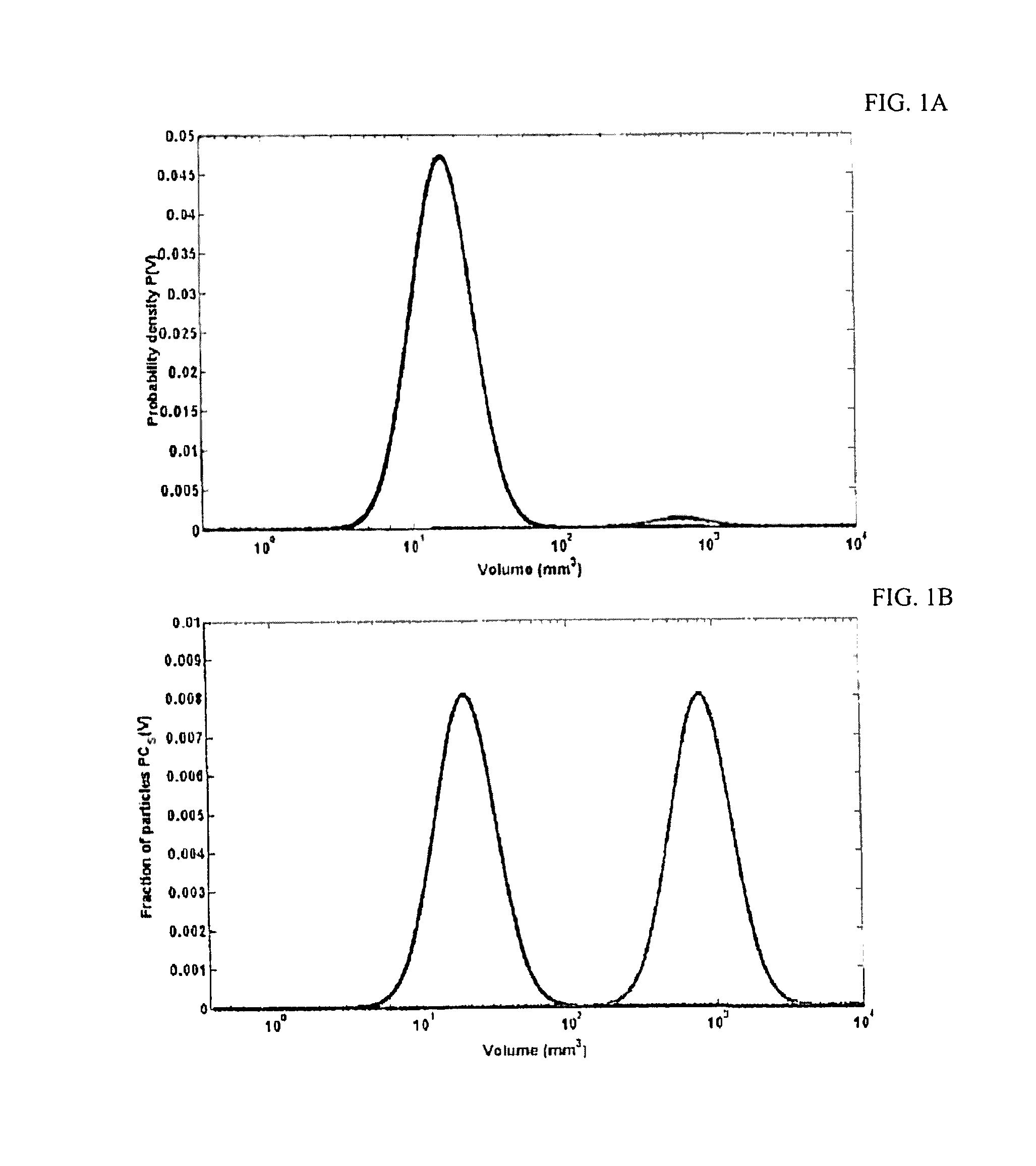
[0149]This is an example of the production of a dense powder for additive manufacturing purposes without using the GCDEP. Ti 6-4 (Ti-6Al-4V, or titanium containing (by weight) about 6% aluminum, 4% vanadium, and some minimal trace elements, including but not limited to iron and oxygen). In this example, two groups of Ti 6-4 particles of commercial purity with a large difference in averages particle sizes are used to produce a compacted metal powder with porosity of approximately 18%. The first group of particles exhibit approximately normally distributed volumes with average particle volume of about 8,000 μm3 (effective diameter of about 25 μm) and a small diameter standard deviation of 5 μm. The volumes of the second group are approximately log-normally distributed according to effective diameters (meaning an approximately normally distributed passing curve, and also volume probability density function, as a function of the logarithm of particle effective diameter or logarithm of p...

example 2

[0150]This is an example of the production of a dense powder for additive manufacturing purposes without using the GCDEP. 316 Stainless Steel (approximately 16.5% carbon, 12% chromium, 3% nickel, 1.4% molybdenum, 0.8% silicon, and trace phosphorus, sulfur, other elements). In this example, stainless steel particles of commercial purity in a single group exhibiting a continuous, approximately log-normally distributed size (diameter) probability density function with average particle effective diameter of about 50 nm (effective volume of 65,000 nm3), sphericity of 0.86, and frictional coefficient of 0.52, are used to produce a powder with porosity of about 20%. To accomplish this, the geometric standard deviation of the particle group must be about 5.5 μm, meaning that 5% of the total volume of particles will be greater than 1 mm in diameter (and 40% greater than 100 μm in diameter). In this case, for additive manufacturing, a vibration step will be advantageous in reducing porosity, ...

example 3

[0151]This is an example of the production of a dense granular composite using the GCDEP. Two groups of flint glass (also called soda-lime) beads with high sphericity >0.98 and low static coefficient of friction <0.05 are to be mixed to form a macroscopic filter. The larger group of beads are 10 mm in diameter and the smaller are 2 mm in diameter. The bead mixtures are highly uniform, i.e., the standard deviation of the volume probability density function of each group is approximately zero. Referring to Table 1, a catalogue of various critical porosity values for simulated mixtures of frictionless spheres at various small to large average sphere diameter (and volume) ratios (simulations conducted using the TJ algorithm), the minimum porosity of 21.6% is found to occur at a relative volume fraction of small spheres of 20.6%. No compaction or vibration step is necessary to achieve this porosity; in fact, excess vibration will result in phase separation of the beads at these size rati...


PUM

PropertyMeasurementUnit
porosityaaaaaaaaaa
volume fractionaaaaaaaaaa
porosityaaaaaaaaaa

Abstract

The present invention relates to granular composite density enhancement, and related methods and compositions. The application where the properties are valuable include but are not limited to: 1) additive manufacturing (“3D printing”) involving metallic, ceramic, cermet, polymer, plastic, or other dry or solvent-suspended powders or gels, 2) concrete materials, 3) solid propellant materials, 4) cermet materials, 5) granular armors, 6) glass-metal and glass-plastic mixtures, and 7) ceramics comprising (or manufactured using) granular composites.

Description

FIELD OF THE INVENTION[0001]This invention was made with government support under grant numbers DMR-0820341 and DMS-1211087 awarded by the National Science Foundation, The government has certain rights in the invention.BACKGROUND[0002]A granular material, or granular composite, is an accumulation of constituent particles, where each constituent has a pre-determined geometry (size and shape) that remains approximately fixed when the constituents are placed in close proximity and pressed against one another, for example, by gravity. In a granular composite, the constituents may also be suspended in a solvent or liquid or held approximately or exactly fixed in place by a “paste” or “glue”. Granular composites are ubiquitous throughout industry, research labs, and the natural world. Common examples of granular composites in the natural world include dirt, sand, and gravel; common examples of man-made granular composites include concrete, bird shot, sugar, baby powder, solid propellants,...

Claims


Application Information

Patent Timeline
Patent Type & Authority Applications(United States)
IPC IPC(8): B22F7/00C04B35/626C04B35/111C04B35/547C04B20/00C03C3/04C03C12/00B33Y10/00B33Y70/00B23K26/00B23K26/354B28B1/00B29C45/00B29C67/00B22F3/105C22C14/00C22C38/56C22C38/44C22C38/02C22C38/00C22C32/00B22F3/11C04B35/56B22F1/052B22F1/065
CPCB22F7/008B22F2302/10C04B35/62695C04B35/111C04B35/547C04B20/0096C03C3/04C03C12/00B33Y10/00B33Y70/00B23K26/0081B23K26/354B28B1/001B29C45/0001B29C67/0081B22F3/1055C22C14/00C22C38/56C22C38/44C22C38/02C22C38/002C22C32/0052B22F7/002B22F3/11C04B2235/3847C04B2235/405C04B2235/608C04B2235/446C04B2235/3217C04B2235/528C04B2235/5436C04B2235/5427B29K2105/251B29K2105/0064B22F2998/10B22F2301/205B22F2301/35B22F2301/15C04B35/5626C04B35/56C04B2235/5445C04B2235/5472C04B28/02C22C1/0458C22C29/08B22F2999/00C22C1/08B29C64/153B29C64/165B29C64/371B29C64/268Y02P10/25B22F1/052B22F1/065B22F10/34B22F10/28B33Y70/10C04B14/048C04B14/06C04B20/0076B22F2202/01B22F7/02B23K26/342B33Y30/00B33Y40/00
Inventor HOPKINS, ADAM BAYNETORQUATO, SALVATORE
Owner THE TRUSTEES FOR PRINCETON UNIV
Why Eureka
Try Eureka