X-ray fluorescence system with high flux and high flux density

a fluorescence system and flux density technology, applied in the field of micro-xray fluorescence systems, can solve the problems of insufficient conventional x-ray sources using electron bombardment, difficult design and construction of illuminators for x-ray applications, and high cost of operation, and achieves high thermal conductivity, high electron density, and efficient heat drawing out of x-ray generating materials.

Inactive Publication Date: 2017-02-16
SIGRAY INC
View PDF0 Cites 36 Cited by
  • Summary
  • Abstract
  • Description
  • Claims
  • Application Information

AI Technical Summary

Benefits of technology

[0039]The higher brightness is achieved in part through the use of novel configurations for x-ray targets used in generating x-rays from electron beam bombardment. These x-ray target configurations may comprise a number of microstructures of one or more selected x-ray generating materials fabricated in close thermal contact with (such as embedded in or buried in) a substrate with high thermal conductivity, such that the heat is more efficiently drawn out of the x-ray generating material. This in turn allows bombardment of the x-ray generating material with higher electron density and / or higher energy electrons, which leads to greater x-ray brightness and therefore greater x-ray flux.
[0040]A significant advantage to some embodiments is that the orientation of the microstructures allows the use of an on-axis collection angle, allowing the accumulation of x-rays from several microstructures to appear to originate at a single origin, and can be used for alignments at “zero-degree takeoff angle” x-ray generation. The linear accumulation of x-rays from the multiple points of origin leads to greater x-ray brightness.
[0041]Some embodiments of the invention additionally comprise x-ray optical elements that collect the x-rays from the source and focus them to spots down to 1 micron in diameter. The x-ray optical elements may comprise paraboloid optics, ellipsoidal optics, polycapillary optics, or various types of Wolter optics and systems comprising combinations thereof. The high collection and focusing efficiency achievable using these optical elements in grazing incidence geometries (where total external reflection occurs) helps achieve high flux density in tightly focused spots.

Problems solved by technology

Designing and constructing illuminators for applications of x-rays can therefore be particularly challenging.
For scientific studies of materials, where high brightness may be needed to obtain adequate signal-to-noise ratios over a range of x-ray energies, conventional x-ray sources using electron bombardment are simply not adequate.
However, these facilities are large, often occupying acres of land, and expensive to operate, and obtaining beamtime can take months of waiting.
The main problem for producing such a system is the lack of a suitable system with an x-ray source and efficient optics for achieving a tightly focused, high flux and high flux density x-rays.
However, synchrotrons are large facilities, often taking up acres of land, and beam time is not available for routine analysis.
Laboratory systems have been designed using similar x-ray optics, but typically cannot achieve the brightness or x-ray flux possible with synchrotron systems.
The perceived disadvantage of laboratory microXRF is that the excitation spot is too large (typically around 30 microns).
The spot size is limited due to the low throughput at smaller spot sizes, caused by a combination of low flux at the object under examination and low solid angle of collection for the x-ray fluorescence.
Though LA-ICPMS generally offers lower (better) relative detection limit for metals with Z>30 and a unique ability to detect isotopes, it is destructive of the specimen (via ablation), has an inferior absolute detection limit, and suffers from polyatomic interference of many elements with Z<30 for complex matrix materials, like biological specimens.
Furthermore, the detection sensitivity (both absolute and relative) is highly compromised for non-metals (such as sulfur (S), phosphorous (P), and selenium (Se)) and especially halogens (such as fluorine (F), chlorine (Cl), or bromine (Br)) due to their low ionization cross-sections and polyatomic interference.
However, the sensitivity and spatial resolution of these laboratory systems has remained limited.
However, trying to drive too much electron energy into too small a spot on the x-ray target can lead to material damage, limiting the brightness achievable.
However, the optical system needed focus tightly and achieve high flux density at the object can be difficult to achieve.
A limitation for such an optical system arises from the poor reflectivity of most materials at most angles of incidence.
This makes the fabrication of practical refractive lenses, analogous to optical lenses, very difficult.
Aside from the practical limitations on the amount of x-rays that can be collected and focused by the optical system, the major practical limitation in x-ray source brightness is limitation of the electron density and electron power incident on the x-ray target to prevent target melting or evaporation.
mechanical motion (such as rotating target anodes to distribute the heat deposition over a larger area) have been designed, but are still limited in the amount of brightness and therefore x-ray flux that can be achieved.

Method used


Image

  • X-ray fluorescence system with high flux and high flux density
  • X-ray fluorescence system with high flux and high flux density
  • X-ray fluorescence system with high flux and high flux density

Examples


Embodiment Construction

1. A Basic Embodiment of the Invention

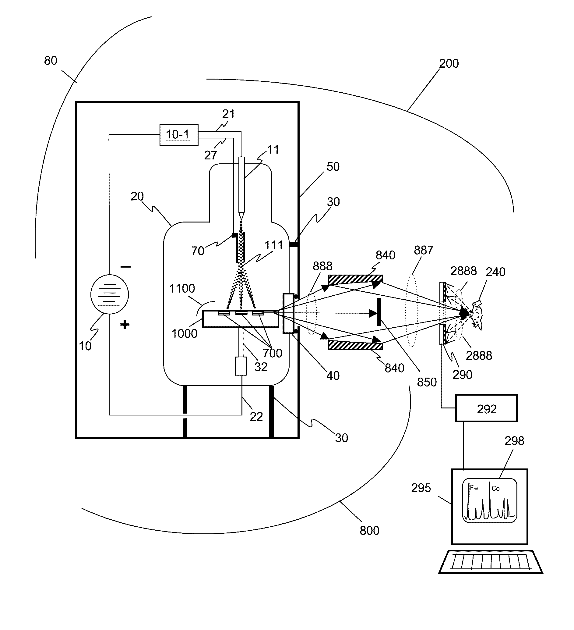
[0091]FIG. 7 illustrates an embodiment of an x-ray fluorescence system 200 comprising an illumination system according to the invention. The fluorescence system 200 comprises an illumination system 800 which comprises an x-ray source 80 and an x-ray optical train 840. The fluorescence system 200 additionally comprises a detector 290 with analysis electronics 295. The source 80 comprises a vacuum environment (typically 10−6 torr or better) commonly maintained by a sealed vacuum chamber 20 or active pumping, and manufactured with sealed electrical leads 21 and 22 that pass from the negative and positive terminals of a high voltage source 10 outside the tube to the various elements inside the vacuum chamber 20. The source 80 will typically comprise mounts 30 which secure the vacuum chamber 20 in a housing 50, and the housing 50 may additionally comprise shielding material, such as lead, to prevent x-rays from being radiated by the source 80 in unwa...


PUM

PropertyMeasurementUnit
thicknessaaaaaaaaaa
energy bandwidthaaaaaaaaaa
refractive indexaaaaaaaaaa

Abstract

We present a micro-x-ray fluorescence (XRF) system having a high-brightness x-ray illumination system with high x-ray flux and high flux density. The higher brightness is achieved in part by using x-ray target designs that comprise a number of microstructures of x-ray generating materials fabricated in close thermal contact with a substrate having high thermal conductivity. This allows for bombardment of the targets with higher electron density or higher energy electrons, which leads to greater x-ray flux. The high brightness / high flux x-ray source may then be coupled to an x-ray optical system, which can collect and focus the high flux x-rays to spots that can be as small as one micron, leading to high flux density at the fluorescent sample. Such systems may be useful for a variety of applications, including mineralogy, trace element detection, structure and composition analysis, metrology, as well as forensic science and diagnostic systems.

Description

CROSS-REFERENCE TO RELATED APPLICATIONS[0001]This patent application is a Continuation-in-Part of U.S. patent application Ser. No. 14 / 544,191, filed Dec. 5, 2014 and soon to issue as U.S. Pat. No. 9,449,781, which is hereby incorporated by reference in its entirety, and which in turn claims the benefit of U.S. Provisional Patent Application No. 61 / 912,478, filed on Dec. 5, 2013, 61 / 912,486, filed on Dec. 5, 2013, 61 / 946,475, filed on Feb. 28, 2014, and 62 / 008,856, filed on Jun. 6, 2014, all of which are incorporated herein by reference in their entirety. The present application is also a Continuation-in-Part of U.S. patent application Ser. No. 14 / 636,994, filed Mar. 3, 2015 and soon to issue as U.S. Pat. No. 9,448,190, which is hereby incorporated by reference in its entirety, and which in turn claims the benefit of U.S. Provisional Patent Application No. 62 / 008,856, filed Jun. 6, 2014; 62 / 086,132, filed Dec. 1, 2014, and 62 / 117,062, filed Feb. 17, 2015, all of which are incorporate...

Claims


Application Information

Patent Timeline
Patent Type & Authority Applications(United States)
IPC IPC(8): H01J35/14H01J35/18H01J35/08G01N23/223
CPCH01J35/14H01J35/08H01J35/18G01N23/223G21K1/06H01J2235/081H01J2235/086H01J35/147
Inventor YUN, WENBINGLEWIS, SYLVIA JIA YUNKIRZ, JANOS
Owner SIGRAY INC
Why Eureka
Try Eureka