Energy-saving and endurable auto electric water pump

a technology of auto electric water pump and electric motor, which is applied in the direction of pump components, non-positive displacement fluid engines, liquid fuel engine components, etc., to achieve the effects of improving the service life of the pump, reducing the temperature of the controller, and simple structur

Active Publication Date: 2017-03-23
FEILONG AUTO COMPONENTS CO LTD
View PDF10 Cites 25 Cited by
  • Summary
  • Abstract
  • Description
  • Claims
  • Application Information

AI Technical Summary

Benefits of technology

[0021]In the present invention, the water cooling mechanism is set on the controller of the electric water pump. The water cooling mechanism and the motor water pump share one water-cycling system jointly and the structure is simple, which can effectively reduce the temperature of the controller and improve the service life of the pump.
[0022]In the present invention, the structure of the auto electric water pump is simple, the motor assembly and the impeller assembly are separated by the isolation sleeve, and water outlet passage is set on the distance sleeve, so that water cannot enter the motor assembly and controller assembly, thus it can play a protective role for the electrical system. At the same time, the manufacturing technology of separation method that dividing the motor assembly and impeller assembly by isolation sleeve is simple, and the manufacturing costs is low, which can effectively reduce the noise of the electric water pump during the running time and increase the service life of the electric water pump.
[0023]In the present invention, the impeller assembly stopper mechanism is set at the top of the rotating axis of the auto electric water pump, and adds axial stop functions to the rotor during operation, which can effectively prevent axial movement when the rotation axis moves at high speed and improve the service life of the auto electric water pump and stability of operation.

Problems solved by technology

Mechanical pumps rely on the engine, and the fixed rate between pump speed and engine speed cannot meet the cooling requirements at low speed and high load, and when the engine stops, it is unable to meet the cooling requirements of main drive motor and other components of new energy vehicles as well as water supply requirements of motor homes.
The brush electric water pump has poor anti-electromagnetic interference capability, and the brush tends to produce sparks that disturb other electronic devices.
At the same time, influenced by the reversing carbon brush wear, the brush electric pump has a short service life, not suitable for new energy vehicles.
(1) The magnet of brushless DC magnetic drive pump and impeller are molded into a integrally composed rotor through injection, there is a sleeve in the center of the rotor fixed in the housing by high performance ceramic axis, and the stator portion of the motor and the circuit board is potted in the pump body by epoxy glue, thus the existing water pump has followings defects: difficulty of manufacturing technology, high production costs, difficult repair and media leaks, and the waterproof performance is not good, which affects the use of the motor. There are some motor pumps with separated rotor and impeller to the existing motor pumps, such as Publication No. CN 204591691U with the name of DC Brushless Auto Electric Water Pump. With distance sleeve, there is a cavity to accommodate the rotor. At the center of the inner bottom surface of the cavity, there is a lug boss to fix the pump shaft, one end of the shaft insert into the lug boss, rotation and axial movement are not allowed, and the other end of the shaft is inserted in the sleeve of the shaft head holder inside the pump head to separate the rotor and impeller in different spaces, which effectively prevents the medium leakage problems in the water pump, but with the problems of complex structure and inconvenient dismantling. Furthermore, the outlet of the DC brushless auto electric water pump faces the impeller, making the water flow be thrown out rapidly by a centrifugal force through the acceleration of the impeller, the noise of the water pump is large, the operation is unsteady and the service time of electric water pump is short.
(2) In addition, in the operation of water pump motor, the motor controller is easier to go wrong, the temperature increasing of motor is fast in the operation process of motor, and it keeps high temperature during the operation. It is likely to cause the controller burned and may reduce the life of the controller. Generally, the cooling equipment of the existing machine controller has heat sink or silicone pad and reduces the temperature of the controller through hot and cold air exchange. But the heat sink or silicone pad adopts the way of air heat exchange for heat dissipation, on one hand, the hot air generated by heat exchange cannot be exhausted out off the pump timely and as the long time operation of the motor, the cooling effect is decreased gradually, and on the other hand the heat dissipation effect of heat sink and the silicone pad itself is general which cannot effectively reduce the temperature of the controller.
(3) The impeller and rotor of the motor pump mounted together by a rotating shaft, generally the rotation shaft is graphite shaft. Rotation and axial movement exist during the operation. Axial movement can cause damage to the graphite shaft and the unsteady operation of motor. The existing installation methods generally suit the integrally molded impeller and rotor on the rotation shaft, which fix one end of the rotating shaft to the lug boss of the isolation sleeve, and fix the other end on the pump housing through shaft. The rotor moves at high speed, and the above installation cannot solve the problem of axial movement.

Method used


Image

  • Energy-saving and endurable auto electric water pump
  • Energy-saving and endurable auto electric water pump
  • Energy-saving and endurable auto electric water pump

Examples


embodiment 1

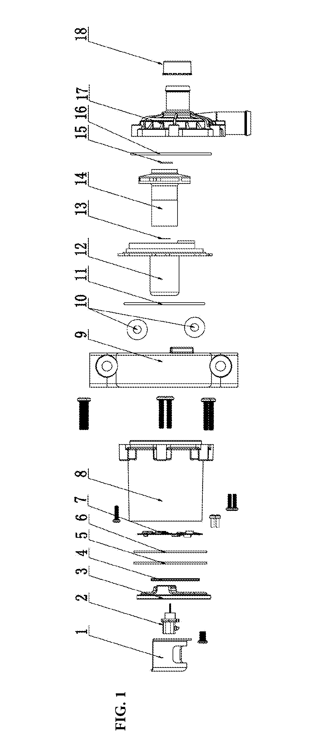
[0037]As shown in FIG. 1, the energy-saving and endurable auto electric water pump is comprised of fixed support 1, electrical connector 2, rear cover of motor 3, controller assembly 7, motor assembly 8, isolation sleeve 12, the impeller assembly 14 and pump head housing 17.

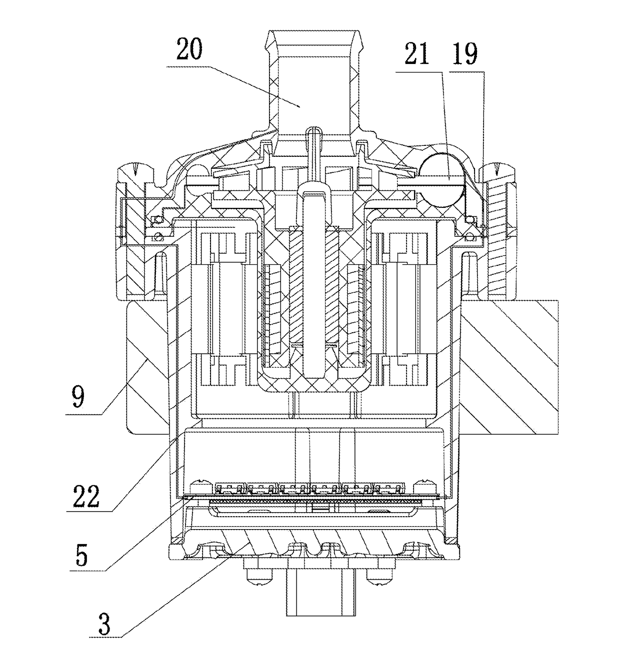
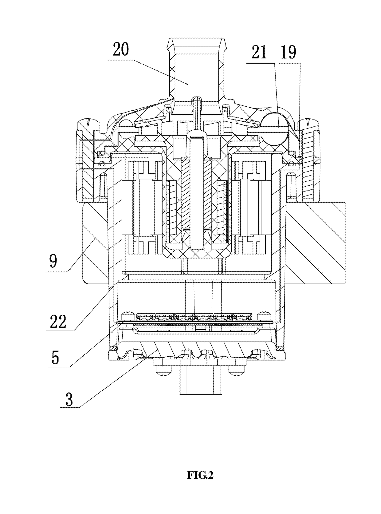
[0038]As shown in FIG. 2, fixed support 1 and electrical connector 2 are mounted on the outer end face of rear cover 3 of motor, the controller assembly 7 is mounted on the inner end face of the rear cover 3 of the motor, and rear cover 3 of the motor is mounted together with the motor assembly 8.

[0039]As shown in FIG. 5, the motor assembly 8 in the present invention includes a three-phase lead 8-6: power on effect; PCB (Printed circuit board) 8-5: fixed three-phase lead 8-6; varnished wire 8-4: produces a magnetic field through electric current after winding, to make motor rotor 14-2 rotate; stator frame 8-3: fixed stator core 8-2, varnished wire 8-4 and PCB 8-5 plate; stator core 8-2: magnetic conductive, colle...

embodiment 2

[0053]The structure of embodiment 2 is basically the same with embodiment 1, except that: as shown in FIG. 8, the upper edge of the barrel portion 12-6 of isolation sleeve 12 extends outwardly and sequentially forms support portion 12-3, annular lug boss 12-2 and step portion 12-1, and a water outlet passage 12-7 is provided on circular lug boss 12-2.

[0054]The step portion 12-1 of isolation sleeve 12 corresponds to water pump housing 17, isolation sleeve 12 plays the role of a gasket to make the sealing effect better. Seal ring 16 can be respectively set for the upper and lower surface of step portion 12-1, the upper seal ring 16 can prevent water leakage in the inner chamber of water pump head housing 17, the lower seal ring 16 can prevent outside water from entering the inner chamber where the motor assembly 8 and controller assembly 7 is placed.

[0055]In this embodiment, the main function of water outlet passage 12-7 is to increase the flow distance and reduce the water flow veloc...

embodiment 3

[0057]This embodiment is basically the same as embodiment 2, except that: as shown in FIG. 10, the stopper mechanism of impeller assembly 12-10 is set at the top of rotating axis 12-5, and the stopper mechanism 12-10 of said impeller assembly is generally pressed in from the top of rotating axis 12-5. The stopper mechanism of impeller assembly 12-10 is in the form of a socket that is provided on the axis in order to avoid the axial movement of the impeller assembly.

[0058]Pressing in the stopper mechanism 12-10 of the impeller assembly from the top of the rotating axis 12-5 can effectively reduce the gap between the stopper mechanism of impeller assembly 12-10 and impeller assembly 14 and reduce the axial movement of the impeller assembly 14 during operation and improve the life of electric water pump.

[0059]Operation process of the present invention:

[0060]Switch on the power, the controller assembly 7 drives the stator to produce a magnetic field and make the rotor 14-2 to rotate, im...


PUM


Abstract

A kind of an energy-saving and endurable auto electric water pump, including fixed support, electrical connector, rear cover of motor, controller assembly, motor assembly, isolation sleeve, impeller assembly and pump head housing, and the said fixed support and said electrical connector are set on the outer end surface of the rear cover of the motor, the controller assembly is mounted on the inner end face of the rear cover of the motor, and rear cover of the motor is mounted together with the motor assembly, the said impeller assembly is installed together with the isolation sleeve through rotating axis, while the water-cooling mechanism is set on the controller assembly. In the present invention, the water cooling mechanism is set on the controller of the electric water pump, which can effectively reduce the temperature of the controller and improve the service life of the pump.

Description

FIELD OF THE INVENTION[0001]The present invention relates to an energy-saving and endurable auto electric water pump, which belongs to the field of electric water pump.BACKGROUND OF THE INVENTION[0002]Auto water pump is a device for conveying engine coolant, which contains mechanical pumps and electric pumps according to the driving mode, and electric pumps can be divided into brush electric water pumps and brushless electric water pumps. Mechanical pumps rely on the engine, and the fixed rate between pump speed and engine speed cannot meet the cooling requirements at low speed and high load, and when the engine stops, it is unable to meet the cooling requirements of main drive motor and other components of new energy vehicles as well as water supply requirements of motor homes. The brush electric water pump has poor anti-electromagnetic interference capability, and the brush tends to produce sparks that disturb other electronic devices. At the same time, influenced by the reversing...

Claims


Application Information

Patent Timeline
Patent Type & Authority Applications(United States)
IPC IPC(8): F04D29/42F04D29/22F04D29/58F04D13/06
CPCF04D29/4293F04D13/06F04D29/22F04D29/5866F05B2240/14F05B2250/70F05B2260/20F04D13/0626F04D13/0686F04D29/5813
Inventor ZHOU, XIANGQINGFENG, FANTANG, JIANHUA
Owner FEILONG AUTO COMPONENTS CO LTD
Why Eureka
Try Eureka