Fuel-oil refining device

a technology of fuel oil and refining device, which is applied in the field of fuel oil refining device, can solve the problems of poor fluidity at ambient temperature, low grade quality of petroleum products, and high viscosity, and achieve the effects of reducing moisture removal processing capacity and processing time, easy recovery of physical properties of fuel oil, and maximizing moisture removal efficiency

Inactive Publication Date: 2017-08-10
ENERBIG
View PDF3 Cites 2 Cited by
  • Summary
  • Abstract
  • Description
  • Claims
  • Application Information

AI Technical Summary

Benefits of technology

[0020]The fuel-oil refining device according to the aspect of the present invention can perform viscosity management and fine pulverization of a bunker-C fuel oil using ultrasound and simultaneously remove moisture and polluted particles using an ion chamber.
[0021]The fuel-oil refining device according to the aspect of the present invention can greatly reduce moisture removal processing capacity and processing time and maximize moisture removal efficiency through spraying of the moisture that is included in a bunker-C fuel oil into a vacuum tank in a multi-baffle method.
[0022]The fuel-oil refining device according to the aspect of the present invention can easily recover the physical property of a fuel oil, provide an accurate quality, and recycle sludge that is extracted in a fuel-oil refining process.

Problems solved by technology

In particular, since the bunker-C fuel oil includes a distilled residual oil as its main component and is not chemically refined, it may have low-grade quality among petroleum products.
Although the bunker-C fuel oil has a high heating value and is inexpensive and economical, it has the drawbacks of high viscosity, poor fluidity at ambient temperature, and difficult fuel supply and treatment.
In addition, the bunker-C fuel oil that is used as a fuel oil may become in the form of a moisture-containing body in which moisture is inevitably resolved during a long-term use in an industrial environment, and the resolved moisture that is contained in the moisture-containing body is a primary factor that expedites trouble and deterioration of an industrial machine.
Saying in addition, since the resolved moisture causes deterioration of various mechanical characteristics, such as corrosion of the device, decrease of lubrication characteristics, oil film breakage, abrasion of mechanical elements, and oxidation of the lubricant, it is required to remove the resolved moisture.
However, according to the prior art as described above, it is required to change the pressure condition in the discharge chamber so that a vacuum pressure state that is balanced with the evaporation chamber and an atmospheric pressure state (or low pressure state that is near to the atmospheric pressure) for discharging the used lubricant are repeatedly formed, and this may cause the operation efficiency of the device to deteriorate.

Method used


Image

  • Fuel-oil refining device
  • Fuel-oil refining device
  • Fuel-oil refining device

Examples


Embodiment Construction

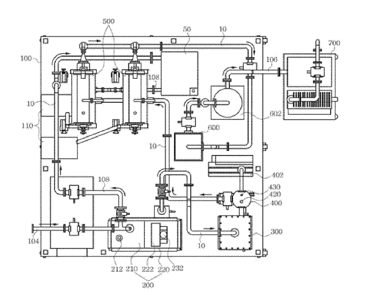
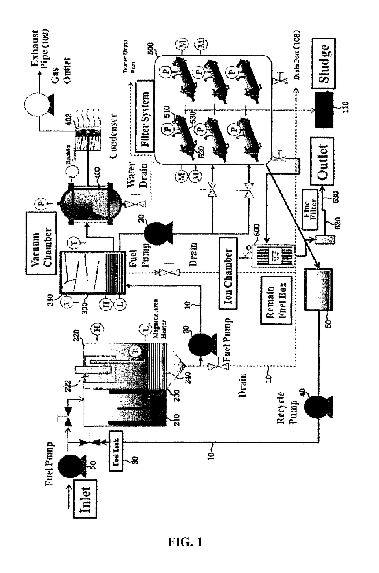
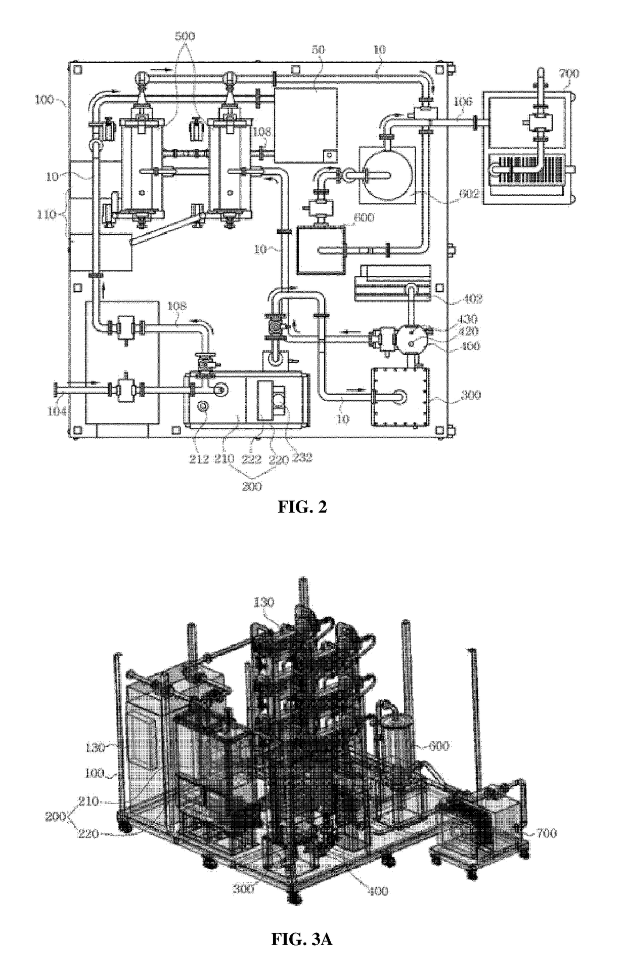
[0032]Hereinafter, preferred embodiments of the present invention will be described in detail with reference to the accompanying drawings. In adding reference numerals to constituent elements in respective drawings, the same reference numerals are used for the same constituent elements across various figures. Further, in explaining the present invention, detailed description of well-known technology and typical technology incorporated herein may be omitted to avoid obscuring the subject matter of the present invention.

[0033]Further, in explaining the constituent elements of the present invention, the terms “first, second, A, B, (a), and (b)” may be used. The terms are used only to discriminate a constituent element from other constituent elements, and the essence, turn, or order of the corresponding constituent element is not limited by the terms. It should be understood that the term “connected to”, “coupled to”, or “contact with” that is used to designate a connection, coupling, o...


PUM

PropertyMeasurementUnit
temperatureaaaaaaaaaa
particle sizeaaaaaaaaaa

Abstract

The present invention is characterized by comprising: a main unit which incorporates a fuel-inflow port for fuel oil supply, a fuel-discharge port for discharging fuel oil that has finished being refined and a drainage discharge pipe for collecting and discharging untreated fuel oil, and a sludge box for storing sludge that has been separated out from the fuel oil; an ultrasound tank which receives fuel oil supplied from the fuel-inflow port, and adjusts the particle size of the fuel oil and the viscosity and surface tension of the fuel oil by means of ultrasound; a vacuum chamber which receives fuel oil supplied from the ultrasound tank, and of which the inside is maintained in a vacuum state such that the specific volume and the surface area of the fuel oil are maximized via a baffle panel; a water-fraction elimination tank of which one side is connected to the vacuum chamber and the other side is connected to a vacuum pump, and which eliminates the water fraction from the fuel oil by using air heated to a high temperature and the reduced pressure of the vacuum state created due to the vacuum chamber; an oil-refining filter which receives fuel oil supplied from the vacuum chamber and filters the received supply of fuel oil by means of centrifugation so as to trap sludge contained in the fuel oil; an ion chamber which eliminates and bums particles including fine foreign matter remaining in the fuel oil in the state after the sludge has been eliminated; and a control panel which is constituted on one surface of the main unit, sets the operating conditions of the ultrasound tank, vacuum chamber and water-fraction elimination tank, and controls whether to provide power for refining the fuel oil.

Description

TECHNICAL FIELD[0001]The present invention relates to a fuel-oil refining device, and more particularly, to a fuel-oil refining device, which can maximize removal of pollutants of polluted fuel oil and moisture in a chemical refining process, easily recover the physical property of the fuel oil, and provide an accurate quality.BACKGROUND ART[0002]In general, various kinds of industrial oils (e.g., mineral oils, vegetable oils, animal oils, synthetic oils, and bunker-C fuel oils) have been used in industrial plants including power generation facilities and hydraulic devices.[0003]In particular, since the bunker-C fuel oil includes a distilled residual oil as its main component and is not chemically refined, it may have low-grade quality among petroleum products. However, the bunker-C fuel oil can be re-processed to produce a lubricant, asphalt, and petroleum coke, and thus it may be called a petroleum product that is made with a clear purpose.[0004]Further, since the bunker-C fuel oi...

Claims


Application Information

Patent Timeline
Patent Type & Authority Applications(United States)
IPC IPC(8): C10G53/02C10M175/02C10M175/00
CPCC10G53/02C10M175/0058C10G2400/10C10G2300/1007C10M175/02C10L2290/34C10L2290/543C10L2290/547C10L2290/08C10L2290/00C10G31/06C10G31/09C10G2300/208C10G2400/02C10G2400/04C10G2400/06C10G2400/08C10M175/00
Inventor KIM, SUNG JOONG
Owner ENERBIG
Why Eureka
Try Eureka