Carbonaceous material for non-aqueous electrolyte secondary battery anode

a secondary battery anode, non-aqueous electrolyte technology, applied in the direction of batteries, cell components, electrochemical generators, etc., can solve the problems of graphite crystal breakdown, repeated increase and return of spacing, and theoretical limits, and achieve high energy density and high doping capacity

Active Publication Date: 2017-08-17
KUREHA KAGAKU KOGYO KK
View PDF12 Cites 4 Cited by
  • Summary
  • Abstract
  • Description
  • Claims
  • Application Information

AI Technical Summary

Benefits of technology

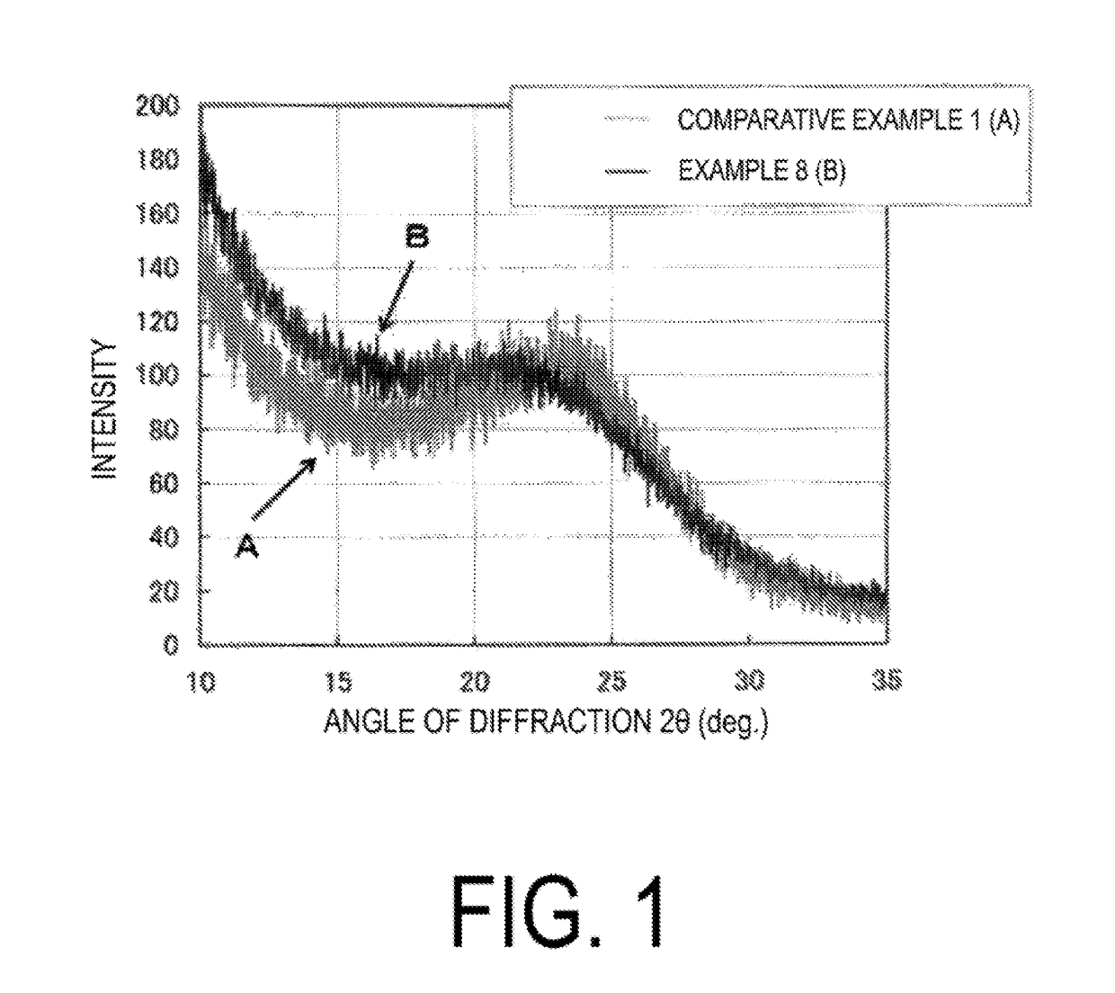
[0025]The carbonaceous material for a non-aqueous electrolyte secondary battery anode of the present invention has a pore structure suitable for storing lithium. This is indicated by the diffraction intensity ratio (R-value) determined by Equation (1) being not greater than 1.25:
[0026](wherein Imax is the maximum value (peak top value) of the 002 diffraction intensity of carbon measured at an angle of diffraction (2θ) within the range of from 20 to 25° as determined by powder X-ray diffraction measured using CuKα rays; Imin is the minimu

Problems solved by technology

High energy density requires a large doping and de-doping capacity of lithium in the anode material, but the theoretical lithium storage capacity of graphitic materials that are mainly used presently is 372 Ah/kg, and there are theoretical limits.
Therefore, with a graphitic material having an advanced graphite structure, repeated doping and de-doping of lithium (repeated charging and discharging in the secondary battery) causes a repeated increase and return of spacing, which tends to lead to the breakdown of graphite crystals.
Accordingly, secondary batteries formed using graphite or a graphitic material having an advanced graphite structure are said to have poor charging and discharging repeating characteristics.
Further, in batteries having such an advanced graphite structure, a problem in which the electrolyte solution tends to degrade easily at the time of battery operation has also been indicated.
On the other hand, alloy-bas

Method used


Image

  • Carbonaceous material for non-aqueous electrolyte secondary battery anode
  • Carbonaceous material for non-aqueous electrolyte secondary battery anode
  • Carbonaceous material for non-aqueous electrolyte secondary battery anode

Examples


example 1

[0153]First, 70 kg of a petroleum pitch with a softening point of 205° C., the atomic ratio H / C of 0.65 and a quinoline insoluble content of 0.4 wt. % and 30 kg of naphthalene were charged into a pressure-resistant container with an internal volume of 300 liters and having a stirring blade and an outlet nozzle, and the substances were melted and mixed while heating. After the heat-melted and mixed petroleum pitch was then cooled, the petroleum pitch was pulverized, and the obtained pulverized product was charged into water at 90 to 100° C., dispersed while stirring, and cooled to obtain a spherical pitch compact. After most of the water was removed by filtration, the naphthalene in the spherical pitch compact was extracted with n-hexane and removed. A porous spherical pitch obtained as described above was subjected to heating and oxidation while being passed through heated air, and heat-infusible porous spherical oxidized pitch was thus obtained. The oxygen content (degree of oxygen...

example 2

[0154]First, 70 kg of a petroleum pitch with a softening point of 205° C., the atomic ratio H / C of 0.65 and a quinoline insoluble content of 0.4 wt. % and 30 kg of naphthalene were charged into a pressure-resistant container with an internal volume of 300 liters and having a stirring blade and an outlet nozzle, and the substances were melted and mixed while heating. After the heat-melted and mixed petroleum pitch was then cooled, the petroleum pitch was pulverized, and the obtained pulverized product was charged into water at 90 to 100° C., dispersed while stirring, and cooled to obtain a spherical pitch compact. After most of the water was removed by filtration, the naphthalene in the spherical pitch compact was extracted with n-hexane and removed. A porous spherical pitch obtained as described above was subjected to heating and oxidation while being passed through heated air, and heat-infusible porous spherical oxidized pitch was thus obtained. The oxygen crosslinking degree of th...

example 3

[0155]A heat-treated carbon coated with pyrolytic carbon was obtained by repeating the operations of Example 1 with the exception that the oxygen content (degree of oxygen crosslinking) was set to 13 wt. % instead of 6 wt. %, that 7 wt. % of NaOH was added instead of 38 wt. % of Na2CO3, that alkali compound washing was not performed, and that the heat-treated carbon was coated with pyrolytic carbon at a temperature of 700° C. instead of 750° C. Next, 5 g of this heat-treated carbon was placed in a horizontal tubular furnace and subjected to reheating treatment for one hour at 1100° C. in a non-oxidizing gas atmosphere to prepare a carbonaceous material 3. Note that the average particle size of the obtained carbonaceous material was 20 μm.


PUM


Abstract

An object of the present invention is to provide a non-aqueous electrolyte secondary battery which has a large charge/discharge capacity, has a small irreversible capacity, and is capable of effectively using an active material.
This object can be achieved by a material for a non-aqueous electrolyte secondary battery anode; a specific surface area determined by a BET method being not greater than 30 m2/g; an atomic ratio (H/C) of hydrogen atoms to carbon atoms determined by elemental analysis being not greater than 0.1; an average particle size being not greater than 50 μm; and a diffraction intensity ratio (R-value) determined by Equation (1) being not greater than 1.25: (wherein Imax is a maximum value of a 002 diffraction intensity of carbon measured at an angle of diffraction (2θ) within a range of from 20 to 25° as determined by powder X-ray diffraction measured using CuKα rays; Imin is a minimum value of a diffraction intensity measured at an angle of diffraction (2θ) within a range of from 15 to 20° as determined by powder X-ray diffraction; and 135 is a diffraction intensity at an angle of diffraction (2θ) of 35° as determined by powder X-ray diffraction).

Description

TECHNICAL FIELD[0001]The present invention relates to a carbonaceous material for a non-aqueous electrolyte secondary battery anode. With the present invention, it is possible to provide a carbonaceous material for a non-aqueous electrolyte secondary battery anode exhibiting a high capacity and excellent charge / discharge efficiency.BACKGROUND ART[0002]As the high functionality of small portable devices such as mobile telephones or notebook personal computers progresses, increases in the energy density of secondary batteries used as the power supplies thereof are anticipated. A non-aqueous solvent-type lithium secondary battery using a carbonaceous material as an anode has been proposed as a secondary battery having a high energy density (Patent Document 1).[0003]In recent years, large secondary batteries, having high energy density and excellent output characteristics, are being mounted in electric vehicles in response to increasing concern over environmental issues. For example, in...

Claims


Application Information

Patent Timeline
IPC IPC(8): H01M4/587H01M10/0525H01M4/66H01M4/133H01M4/62
CPCH01M4/587C01P2006/10H01M4/625H01M4/623H01M4/661H01M10/0525C01B31/02H01M2004/021H01M2004/027H01M2220/20C01P2006/40C01P2006/12C01P2004/61C01P2002/74C01P2002/72H01M4/133Y02E60/10C01B32/00C01B32/05
Inventor SONOBE, NAOHIROSHIMIZU, KAZUHIKO
Owner KUREHA KAGAKU KOGYO KK
Why Eureka
Try Eureka