Circuit board and method for manufacturing same

a technology of circuit board and manufacturing method, which is applied in the direction of dielectric characteristics, conductive pattern formation, thermoplastic polymer dielectrics, etc., can solve the problems of design restrictions on lamination structure, inconvenient mass production of laminated circuit board method, etc., and achieve excellent solder heat resistance and peeling resistance, excellent dimensional stability, and excellent heat resistan

Active Publication Date: 2017-08-17
KURARAY CO LTD
View PDF1 Cites 5 Cited by
  • Summary
  • Abstract
  • Description
  • Claims
  • Application Information

AI Technical Summary

Benefits of technology

[0024]According to the production method of the circuit board concerning the present invention, the circuit board excellent in solder heat resistance and peeling resistance can be provided. Further, the circuit board which is also excellent in dimensional stability at the time of heat treatment can be provided.

Problems solved by technology

However, the method described in Patent Document 2 is not suitable for mass production of laminated circuit boards, because the method requires processing of adhesion surface by polish or an ultraviolet exposure.
The method also imposes design restrictions of lamination structure.

Method used


Image

  • Circuit board and method for manufacturing same
  • Circuit board and method for manufacturing same
  • Circuit board and method for manufacturing same

Examples


example 1

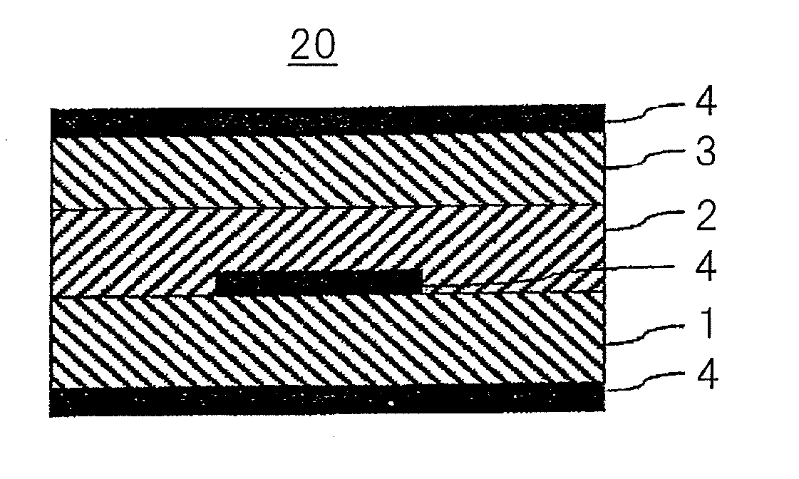
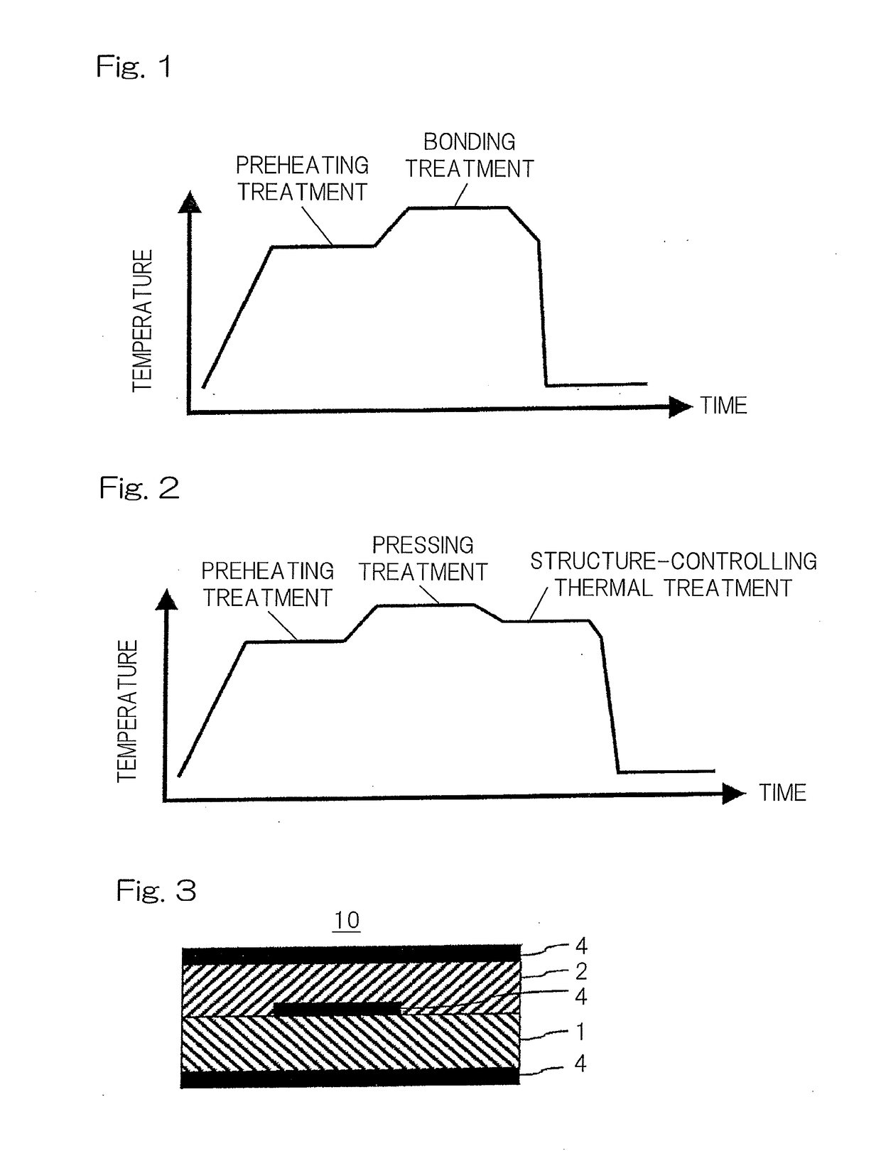
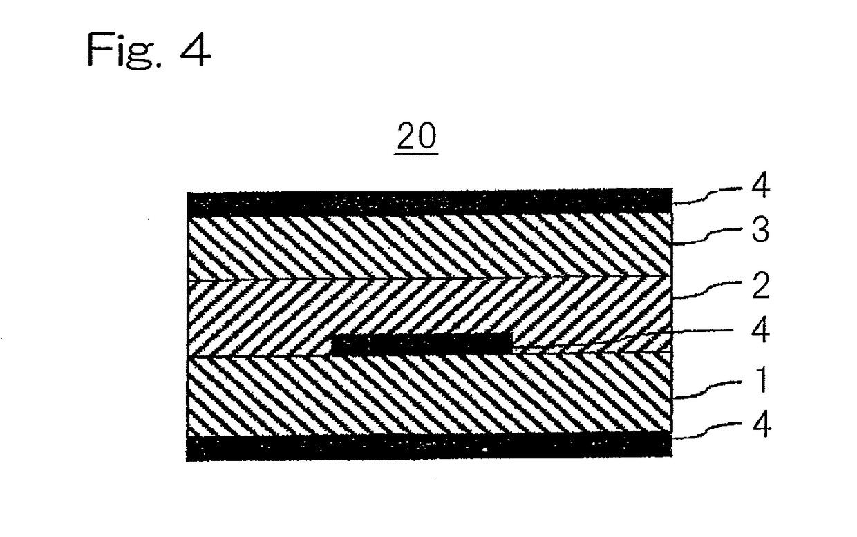
[0110]Onto each surface of a TLCP film having a melting point of 335° C. (Kuraray Co., Ltd., CT-Z, thickness: 50 μm), a rolled copper foil (JX Nippon Mining & Metals Corporation, BHYX-T-12, thickness: 12 μm) was set to be laminated, and using a vacuum hot press apparatus (heating board temperature: 300° C.), thermo-compression-bonding was carried out for 10 minutes under a pressure of 4 MPa to produce a first unit circuit board having a configuration of copper foil / TLCP film / copper foil.

[0111]Onto one surface of a TLCP film having a melting point of 285° C. (Kuraray Co., Ltd., CT-F, thickness: 50 μm), a rolled copper foil (JX Nippon Mining & Metals Corporation, BHYX-T-12, thickness: 12 μm) was set to be laminated, and using a vacuum hot press apparatus (heating board temperature: 275° C.), thermo-compression-bonding was carried out for 10 minutes under a pressure of 4 MPa to produce a second unit circuit board having a configuration of copper foil / TLCP film. Subsequently, circuit pr...

example 2

[0114]Except for changing the adhesion temperature for thermo-compression-bonding of a stacked material into 295° C., a circuit board of Example 2 was obtained using the same material and producing conditions as Example 1. In order to examine dimensional change rate, the second unit circuit board before lamination was subjected to marking by selecting a field (25 cm×25 cm) and pointing 25 marks (punched holes) in total with five rows in the MD direction and five rows in the TD direction. The interval of the opposed rows was 5 cm, and the punched holes in each row countered in the MD direction and the TD direction.

example 3

[0115]Except for changing the adhesion temperature for thermo-compression-bonding of a stacked material into 300° C., a circuit board of Example 3 was obtained using the same material and producing conditions as Example 1.


PUM

PropertyMeasurementUnit
temperatureaaaaaaaaaa

Abstract

Provided are circuit board excellent in interlayer adhesion and solder heat resistance, and production method thereof. The circuit board is produced by a method including: preparing a plurality of at least one kind of thermoplastic liquid crystal polymer (TLCP) films, forming a conductor layer on one side or both sides of a film in at least one of the films to obtain a unit circuit board, laminating the films containing the unit circuit board to obtain a stacked material, conducting thermo-compression-bonding of the stacked material under pressurization to a first temperature giving an interlayer adhesion to integrate the stacked material, carrying out structure-controlling thermal treatment by heating the integrated stacked material at a second temperature which is lower than the first temperature and is lower than a melting point of a TLCP having a lowest melting point out of the plurality of TLCP films.

Description

CROSS REFERENCE TO THE RELATED APPLICATIONS[0001]This application is a continuation application, under 35 U.S.C.§111(a), of international application No. PCT / JP2015 / 080743, filed Oct. 30, 2015, which claims Convention priority to Japanese patent application No. 2014-227321, filed Nov. 7, 2014, the entire disclosure of which is herein incorporated by reference as a part of this application.FIELD OF THE INVENTION[0002]The present invention relates to a laminated circuit board which is excellent in interlayer adhesion and solder heat resistance, and a production method thereof.BACKGROUND ART[0003]In general electronic equipment, such as an information processing device and a communication device, comprises a circuit board. The circuit board usually has a substrate of an insulating material, and a layer of an electrical conducting material (hereinafter referred to as a conductor layer) formed on the substrate. The conductor layer is used to form a circuit. Various kinds of electronic pa...

Claims


Application Information

Patent Timeline
Patent Type & Authority Applications(United States)
IPC IPC(8): H05K3/46H05K1/03H05K3/10
CPCH05K3/4632H05K3/10H05K1/0313H05K2203/0278H05K2201/0129H05K2201/0141H05K1/0393B29C66/034B29C66/45B32B15/08B29C66/7352B29C66/742B29C66/91933B32B38/0036B29C65/02H05K3/4635H05K2201/0355H05K2203/111H05K2203/1178H05K2203/1194B29L2031/3425B29C66/1122B29C66/7392B29C66/73921B29C66/91411B29C66/91445H05K3/022
Inventor TAKAHASHI, TAKESHINAKASHIMA, TAKAHIROONODERA, MINORUHARA, TETSUYA
Owner KURARAY CO LTD
Why Eureka
Try Eureka