Niobium solid electrolytic capacitor

a solid electrolytic capacitor and niobium technology, applied in the direction of liquid electrolytic capacitors, electrolytic capacitors, electrolytic capacitors, etc., can solve the problems of inability to solve problems, inability to niobium solid electrolytic capacitors, and large problems in the forming (hereinafter, referred to as molding) step, so as to prevent the degradation of niobium at injection molding, good capacitor properties, good capacitor properties

Inactive Publication Date: 2005-06-30
SAN DENSHI INDS
View PDF7 Cites 6 Cited by
  • Summary
  • Abstract
  • Description
  • Claims
  • Application Information

AI Technical Summary

Benefits of technology

[0012] By employing the aforementioned means, degradation of niobium at injection molding can be prevented to allow to provide a niobium solid electrolytic capacitor havi...

Problems solved by technology

However, there were many problems in the case of an electrolytic capacitor using niobium as an anode member that a leakage current (LC) tended to become large, an aging treatment (an operation for insulating a defective portion of a dielectric oxide film by applying a direct-current voltage according to the polarity of a capacitor for a long period of time) for reducing the leakage current did not achieve easily a desired effect, and a value of capacitance was apt to vary depending on a direct-bias voltage, which problems were impossible to be solved by converting simply the technique employed when tantalum was used as the anode body.
However, the final production step, that is, a forming (hereinafter, referred to as molding) step is also faced with a large problem.
However, since an injection pressure at injection molding is large, the dielectric coating film on the surface of the anode body is injured due to a mechanical damage at the injection molding to result in an increase in the leakage current supposedly caused by this.
However, when a capacitor element using an anode body with niobium as the main component is molded by the same method as that for the tantalum element, the finished capacitor often has been heavily deteriorated, can not be repaired sufficiently by being subjected to a well known ...

Method used


Image

  • Niobium solid electrolytic capacitor
  • Niobium solid electrolytic capacitor
  • Niobium solid electrolytic capacitor

Examples


example 1

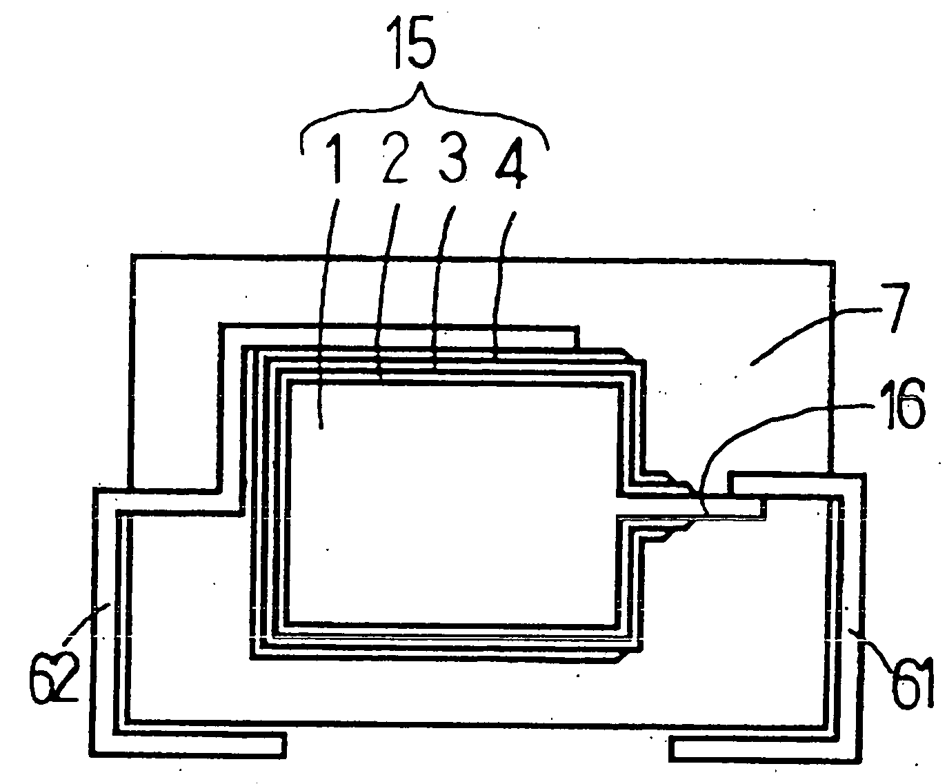
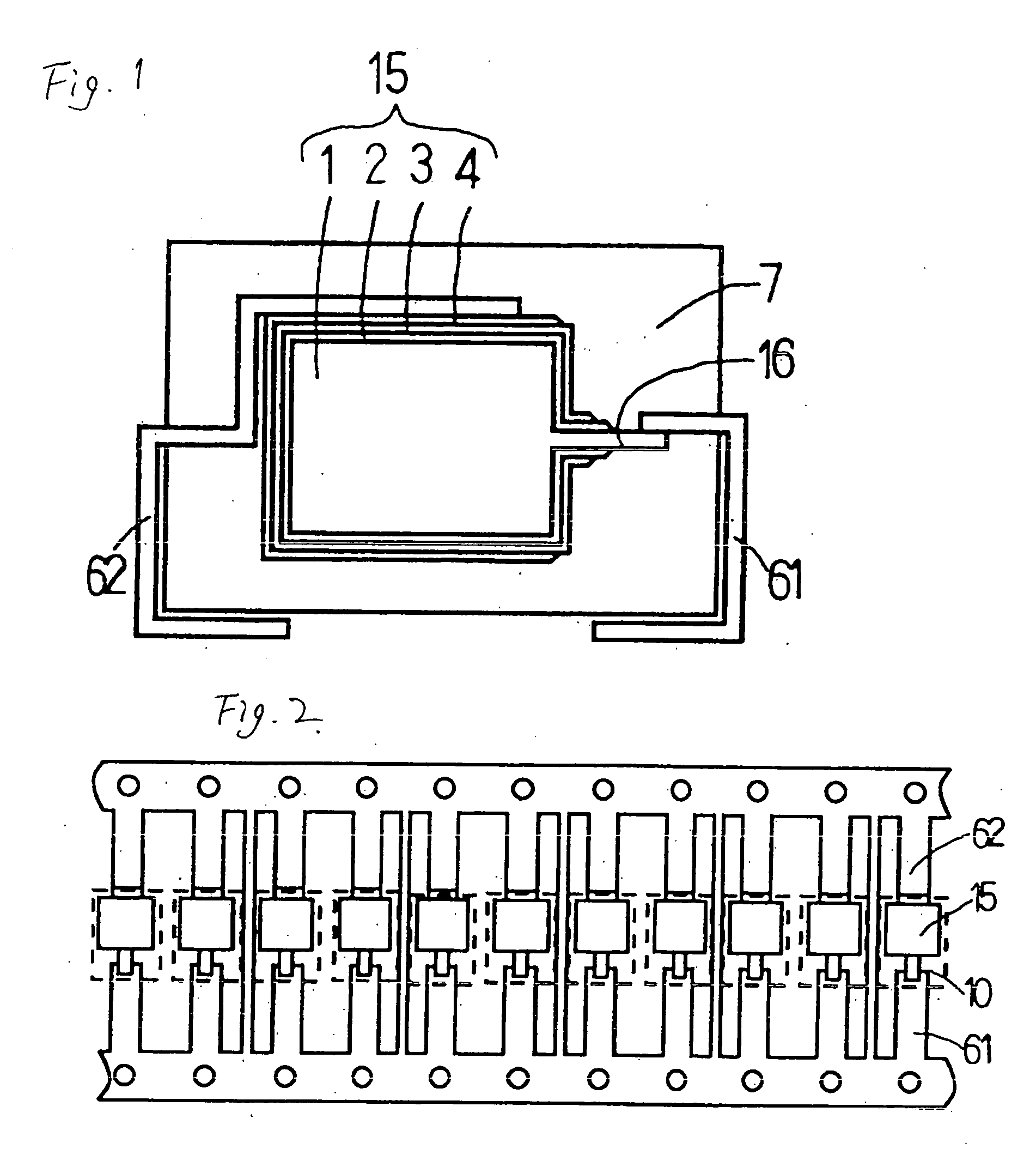
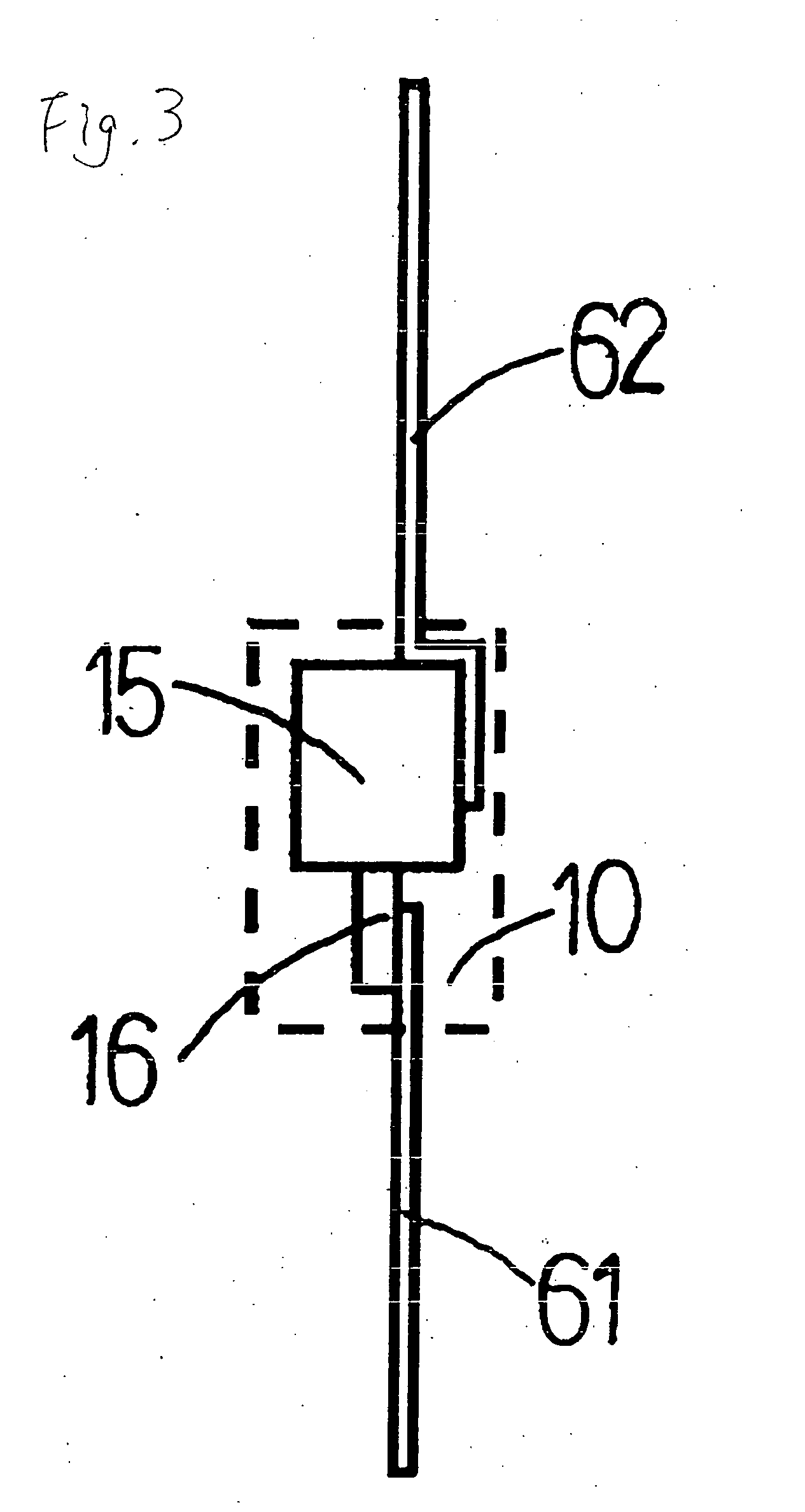
[0019] A capacitor element was formed by chemically converting an element prepared by sintering 60 mg of niobium powder having a CV product of 97000 μFV / g with an implantation niobium wire in an aqueous nitric acid solution at 45 V and then forming a solid state electrolyte layer constituted of polypyrrole and a cathode lead-out layer constituted of a carbon layer and silver paste layer in order, which was subjected to naked pre-aging at 125° C. and 10 V for 1.5 hours. Subsequently, the capacitor element was attached with an anode terminal and cathode terminal by a well-known way. The resultant was set in accordance with a cavity of an injection mold heated at 150° C. The injection mold was injected with a liquid silicone resin having a viscosity of 51000 poise (hereinafter, represented as P) and post solidification hardness of 71 Hs over 5 seconds with 10 atm, which was held for 20 sec to cure to form a sheath resin. Thus, a niobium solid electrolytic capacitor of 100 μF / 10V was pr...

example 2

[0020] A niobium solid electrolytic capacitor was prepared by the same way as in Example 1, except for setting a capacitor element in an injection mold heated at 120° C., injecting a flame-resistant liquid silicone resin having a viscosity of 7000 P and a post solidification hardness of 55 Hs over 5 seconds with 10 atm to be held for 100 seconds to cure, at aforementioned injection molding.

example 3

[0021] A niobium solid electrolytic capacitor was prepared by the same way as in Example 1, except for attaching the capacitor element with an anode terminal and cathode terminal followed by dipping in polyimide silicone SMP-2001 (made by Shin-Etsu Chemical) to form an undercoating on the surface of the capacitor element, then, conducting a primer treatment to the capacitor element, anode terminal and cathode terminal, and then injecting a liquid silicone resin having a viscosity of 6100 P and post solidification hardness of 79 Hs.


PUM

PropertyMeasurementUnit
Hardnessaaaaaaaaaa

Abstract

A solid electrolytic capacitor constituted by forming a dielectric coating film, a solid state electrolyte layer, and cathode lead-out layer in order on the surface of an anode body comprising niobium or an alloy containing niobium as the main component to an end of which an anode lead member is implanted to construct a capacitor element, connecting the anode lead member with an anode terminal and connecting the cathode lead-out layer, at the same time, with a cathode terminal, and being covered and sealed by a sheath resin, in that the sheath resin is formed by injecting and filling liquid silicone resin and heat curing molding the same.

Description

BACKGROUND OF THE INVENTION [0001] The present invention relates to a resin mold-type solid electrolytic capacitor using niobium or an alloy containing niobium as the main component as an anode member. [0002] Nowadays, as an anode body of an electrolytic capacitor, a winding of surface-roughened aluminum foil, a single layer body or multilayer body of a surface-roughened aluminum thin plate, a porous sintered body of tantalum powder and the like are frequently used. As material of the anode body, niobium also comes under the spotlight. Niobium is a metal belonging to the same group, i.e., 5A, as tantalum in the periodic table of the elements and having physical properties similar to those of tantalum, has many advantages such as a smaller specific gravity, a larger amount of reserves in the earth curst and a lower kg unit cost compared with tantalum. Therefore, trials to utilize niobium as an anode member of an electrolytic capacitor have been done. However, there were many problems...

Claims


Application Information

Patent Timeline
IPC IPC(8): H01G9/08
CPCY10T29/417H01G9/08
Inventor TAKETANI, YUTAKAHASABA, YOSHIAKISAKAMAKI, MAKOTOITO, TADAHITO
Owner SAN DENSHI INDS
Why Eureka
Try Eureka