
Process to create 3D tissue scaffold using electrospun nanofiber matrix and photosensitive hydrogel

a nanofiber matrix and photosensitive hydrogel technology, applied in the field of polymer fiber production, can solve the problems of fiber matrix losing the porosity needed to grow cells in 3d, and it is not possible with current methods to maintain the alignment of fibers in the fiber matrix, etc., to achieve good mechanical strength, improve the initial and final setting time, and improve the effect of microstructur

Active Publication Date: 2017-08-24
UNIVERSITY OF CENTRAL OKLAHOMA
View PDF0 Cites 12 Cited by
  • Summary
  • Abstract
  • Description
  • Claims
  • Application Information

AI Technical Summary

Benefits of technology

The present invention solves the problem of losing porosity in biomaterial scaffolds when layers of nanofibers are stacked together. The invention allows for the production of higher thickness ENF-based 3D scaffolds for tissue engineering applications. The method involves creating a porous fiber membrane consisting of cross-direction fibers each separated by a gap distance, and controlling the porosity by increasing or decreasing the number of cross-direction fibers. The invention enables the production of cell-encapsulated hydrogels with complex 3D structures using the PCL-ENF-PEGDA scaffold.

Problems solved by technology

A major challenge of using ENF to create a 3D cell culture device is that when nanofiber layers are stacked together more than microns thick, the fiber matrix loses the porosity needed to grow cells in 3D.
In addition, it is not possible with current methods to maintain alignment of fiber in the fiber matrix after depositing more than two or three layers of aligned fiber layers due to the repulsive characteristics of the fiber comprising each of the layers.
The PCL membranes currently available in the market exhibit randomly distributed fibers and therefore have limited applications in producing scaffolds that require more than a few millimeters in thickness for tissue engineering applications.

Method used


Image

  • Process to create 3D tissue scaffold using electrospun nanofiber matrix and photosensitive hydrogel
  • Process to create 3D tissue scaffold using electrospun nanofiber matrix and photosensitive hydrogel
  • Process to create 3D tissue scaffold using electrospun nanofiber matrix and photosensitive hydrogel

Examples


Embodiment Construction

[0048]In brief:

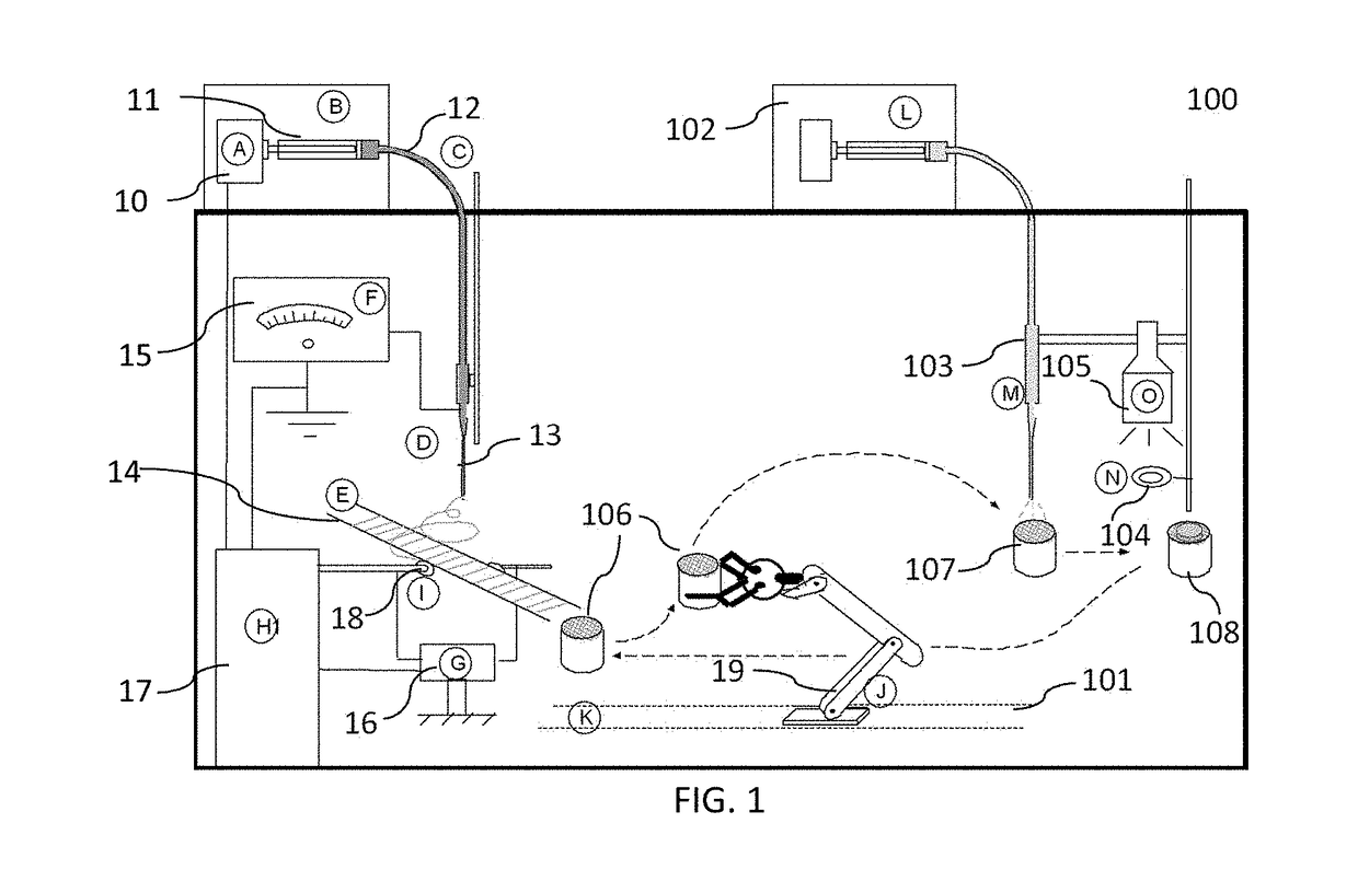
[0049]FIG. 1 is a non-limiting diagram showing a combined electrospin-UV photopolymerization unit for automatic production of 3D scaffold of the present invention. The systems (electrospin and UV polymerization systems) used to produce 3D scaffold can be combined as shown. Using the automatic system as shown any number of Polyethylene Glycol Diacrylate (PEGDA) layer and PCL matrix layers can be used to produce any shape of 3D scaffold. Such scaffold can be used as an engineering scaffold for grafting of natural tissue such as liver, skin, bone etc.

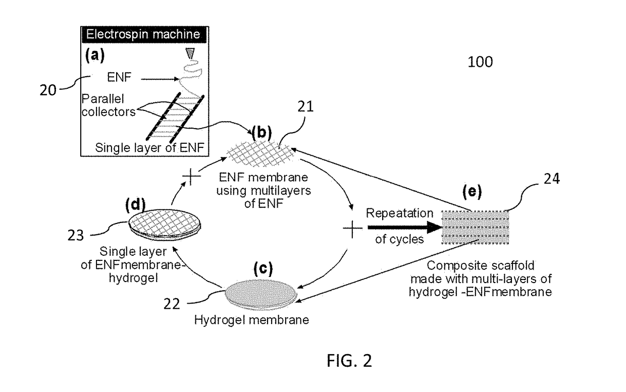
[0050]FIG. 2 is a non-limiting diagram showing a schematic view of the method of the present invention. The invention uses a novel approach of controlled application of aligned electrospun fiber layer and photosensitive biomedical polymer to create 3D scaffolds. The process of creating 3 layers of fiber-polymer matrix is schematically represented. The number of cross aligned fiber layers holds the polymer liquid in place and...


PUM

PropertyMeasurementUnit
thicknessaaaaaaaaaa
thicknessaaaaaaaaaa
diameter×1aaaaaaaaaa

Abstract

A process providing a method to create 3D scaffolds using nano-scale fibers, comprising: deposition and alignment of a plurality of electrospun fiber layers on a substrate; application of a photosensitive biomedical polymer liquid to each fiber layer deposited on said substrate; deposition and cross-alignment of a plurality of electrospun fiber layers on said substrate; retaining said polymer liquid in place using said cross-aligned fiber layers; curing said polymer liquid on top of each fiber layer using UV light.

Description

CROSS REFERENCES TO RELATED APPLICATIONS[0001]This application claims the benefit of U.S. Provisional Patent Application No. 62 / 298,627 filed on Feb. 23, 2016 in the name of Morshed Khandaker and Shahram Riahinezhad, which is expressly incorporated herein by reference in its entirety.STATEMENT AS TO RIGHTS TO INVENTIONS MADE UNDER FEDERALLY SPONSORED RESEARCH OR DEVELOPMENT[0002]This invention was made with government support under Grant Number 5P20GM103447 awarded by the National Institutes of Health. The government has certain rights in the invention.”FIELD OF THE INVENTION[0003]The present invention generally relates to the field of polymer fiber production. More specifically, the invention relates to a process for the development of a thick photosensitive hydrogel scaffold by incorporating hydrogel into electrospun nanofiber membranes.BACKGROUND OF THE INVENTION[0004]Tissue engineering (TE) holds great promise for cultivation of patient-specific tissues for restoring organ funct...

Claims


Application Information

Patent Timeline
Patent Type & Authority Applications(United States)
IPC IPC(8): A61L27/26D06M15/27B33Y10/00B33Y70/00B33Y80/00A61L27/56A61L27/54A61L27/52A61L27/38C12N5/00C12N5/077C12N5/071C12N5/04D01D5/00B29C67/00D06M23/14
CPCA61L27/26B29L2031/753D06M15/27B33Y10/00B33Y70/00B33Y80/00A61L27/56A61L27/54A61L27/52A61L27/3817A61L27/3813A61L27/3804C12N5/0062C12N5/0012C12N5/0655C12N5/0625C12N5/04D01D5/003B29C67/0081D06M2101/32A61L2300/412A61L2430/02C12N2533/30C12N2533/52C12N2533/54C12N2513/00B29K2105/0058D10B2509/00D06M23/14D04H1/728D01F6/625A61L27/48A61L2400/12B29C64/165C08L67/04C08L71/02
Inventor KHANDAKER, MORSHEDRIAHINEZHAD, SHAHRAM
Owner UNIVERSITY OF CENTRAL OKLAHOMA
Learn More