
Method of designing and modifying lithium ion battery cathode materials

a lithium ion battery and cathode material technology, applied in the direction of cell components, sustainable manufacturing/processing, instruments, etc., can solve the problems of low charge capacity, limited application to experimental research, and limited further enhancement of lib performance, so as to achieve higher calculation speed and high precision

Inactive Publication Date: 2017-10-12
NANO & ADVANCED MATERIALS INST
View PDF0 Cites 33 Cited by
  • Summary
  • Abstract
  • Description
  • Claims
  • Application Information

AI Technical Summary

Benefits of technology

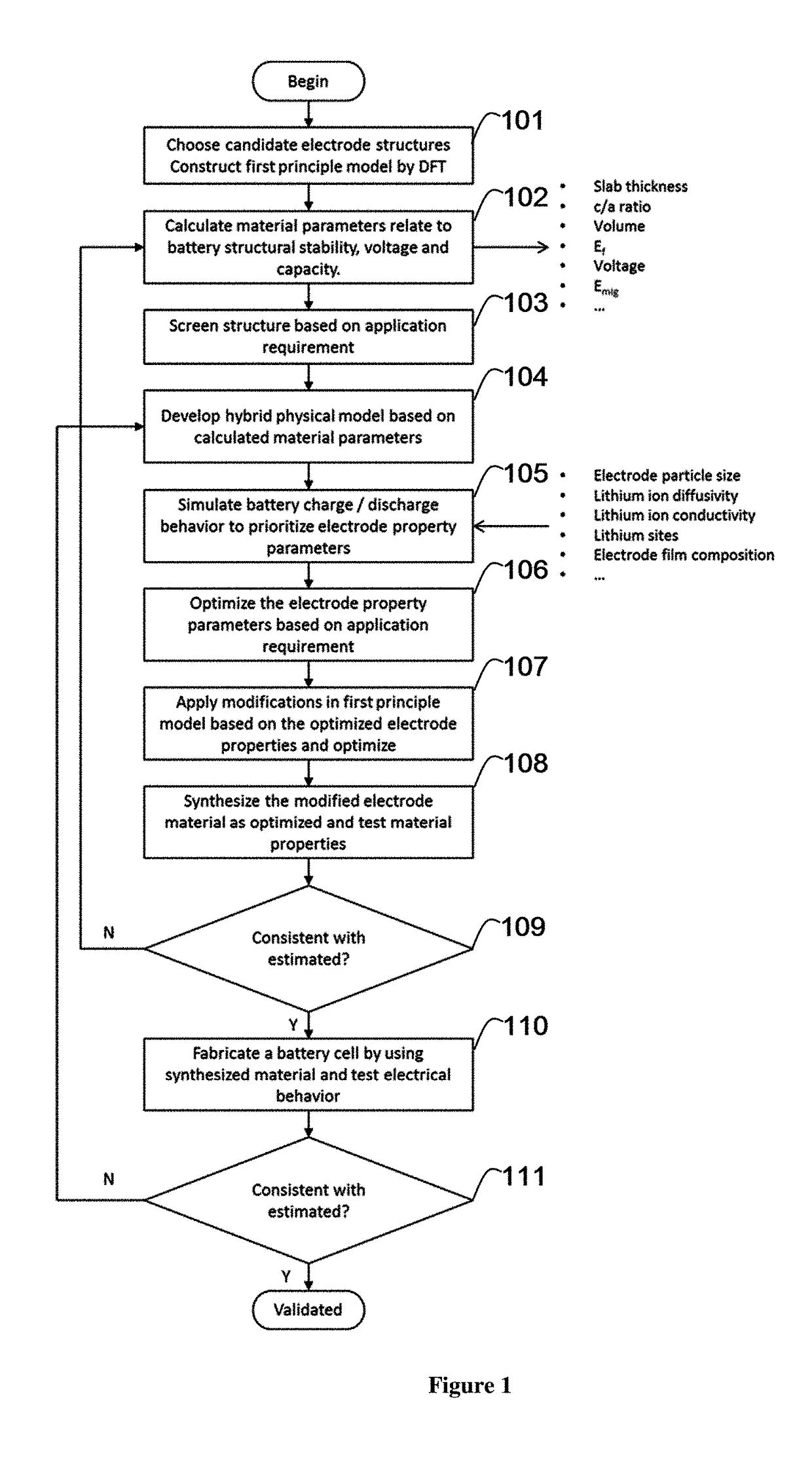
The present invention is a combination of different levels of battery modeling. It can calculate the movement of lithium ions in a battery using atomic-level simulation and input these results into a battery-level simulation. This hybrid model is used to select, modify, and optimize the materials used in a battery. The advantage of this hybrid model is that it provides a balance between higher accuracy and faster calculations. This helps to improve the performance of batteries and optimize their design.

Problems solved by technology

However, due to the intrinsic material properties of this cathode material, besides the toxicity and high material cost of cobalt, further enhancement of LIB performance is also limited.
But its application is limited to experimental research because of difficulties in synthesis and safety concerns due to the thermal runaway reaction.
However its low charge capacity and inferior cycling performance, especially under high temperatures, limit the application of this material to small electrokinetic cells.
Nevertheless, there are still some drawbacks in the multi-transition metal oxides cathode materials to be improved, for instance, phase transformation and thermal stability related safety issue for LNMC as well as the large irreversible first cycle capacity and fast deterioration of capacity after repeated charge and discharge cycles for LLO.
Therefore, it is clear that existing single structured cathodes cannot deliver “perfect” performance for various application requirements.
Furthermore, the identified optimal design for one application usually does not apply to others.
In other words, the whole empirical, iterative, costly and time-consuming design process needs to be repeated for different applications.
However this method is mainly limited to the fundamental material properties estimation without considering the parameters more related to the full-cell electrical behavior, such as electrode material packing density, lithium ion diffusivity in the active / inactive electrode materials, and lithium ion diffusion pathways.

Method used


Image

  • Method of designing and modifying lithium ion battery cathode materials
  • Method of designing and modifying lithium ion battery cathode materials
  • Method of designing and modifying lithium ion battery cathode materials

Examples


example 1

Simulation of Undoped and Mg Doped Li-Rich Layered Oxide (LLO)

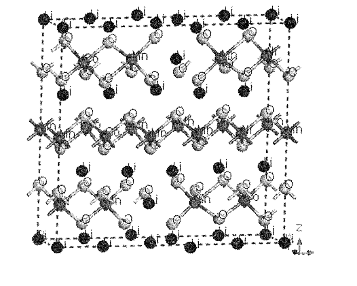
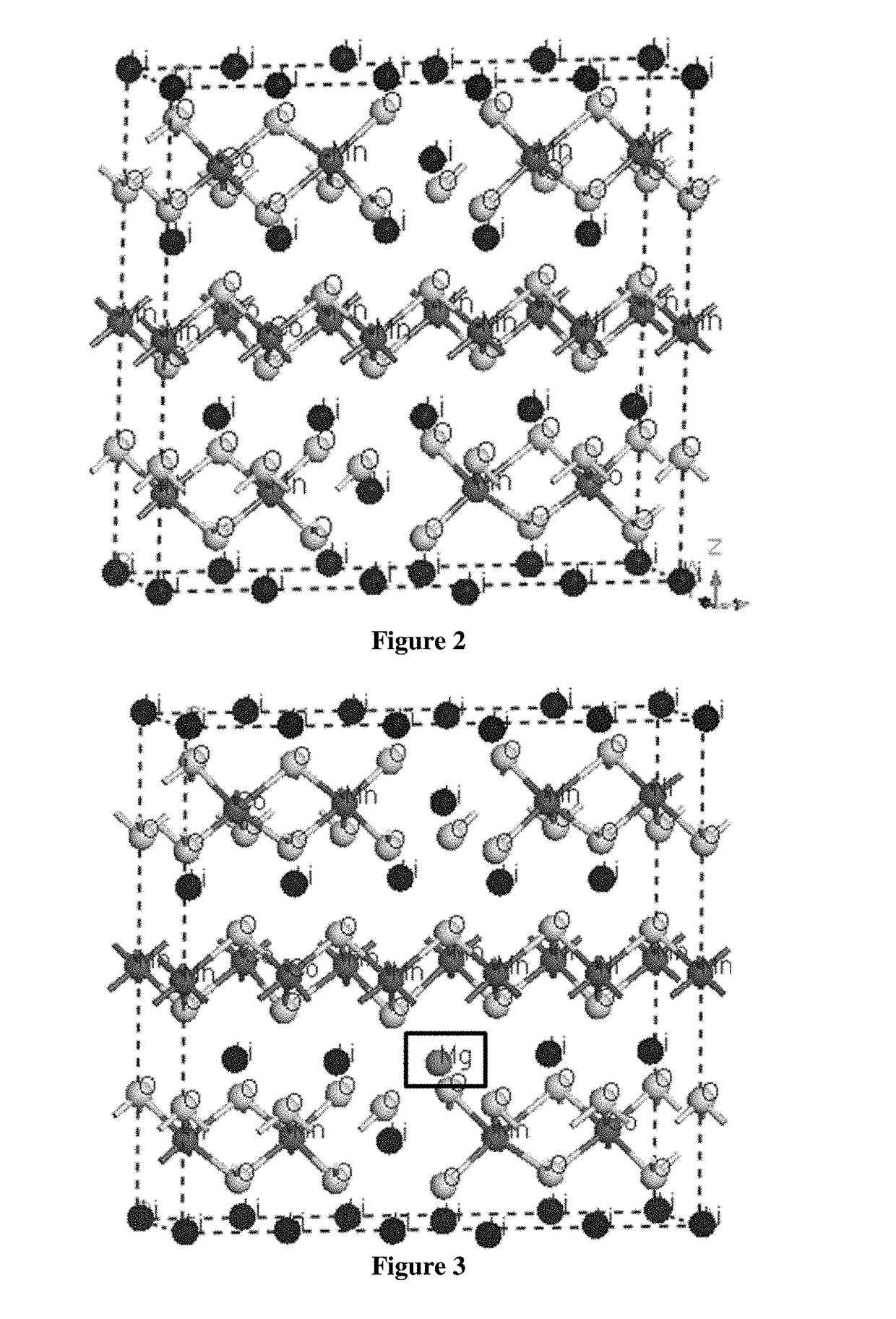
[0118]First principle simulation based on Density Functional Theory (DFT) was conducted by using Material studio CASTEP. Trigonal system with space group of R-3M was constructed. Fractional coordinate for different elements are: Li (0,0,0), O (0,0,0.2594), transition metal (0,0,0.5). Transition metal elements include Ni, Co and Mn. Initial lattice constants were set as a=0.2823 nm and c=1.3890 nm. Then a super lattice was constructed by combining 5×1×1 unit cell. For the calculated Li-rich layered oxide, 2 Li atoms occupied transition metal position. In the super cell, there were totally 17 Li atoms, 3 Co atoms, 3 Ni atoms, 8 Mn atoms and 30 O atoms for the undoped LLO (FIG. 2). For the Mg doped LLO, one Li atom in the Li layer was replaced by Mg atom (FIG. 3).

[0119]Geometry optimization was conducted first with the function of General Gradient Approximation (GGA), cutoff energy of 950 eV, ultrasoft pseudopotential and sp...

example 2

Simulation of Fe Doped Li-Rich Layered Oxide

[0128]The procedure of Example 1 was repeated, except that 1 Co atom was replaced by Fe atom (FIG. 6). The simulation results are shown in Table 3. Fe doped LLO shows larger slab thickness after delithiation (x=0) which is favorable for Li intercalation, and higher c / a ratio indicating a better layered structure. These could contribute to higher charge-discharge efficiency. Fe doped LLO also has smaller volume (x=1) due to the shorter and stronger bond between transition metal and oxygen which can reduce oxygen loss and structure changes, and lower formation energy as compared to undoped LLO indicating more stable structure. These could contribute to better cycle performance. Finally, Fe doped LLO shows much higher voltage and lower migration energy (i.e. higher diffusivity). These could contribute to higher capacity.

TABLE 3the simulation results for undoped and Fe-doped LLO in Example 2Li contentUndoped LLOFe doped LLOSlab thickness (Å)x ...

example 3

[0133]Simulation of Undoped and Al Doped LiMn2O4

[0134]Cubic system with space group of FD-3M was constructed. Fractional coordinate for different elements are: Li (0.125,0.125,0.125), O (0.261,0.261,0.261), Mn (0.5,0.5,0.5). Initial lattice constants were set as a=0.8245 nm. In the unit cell, there were totally 8 Li atoms, 16 Mn atoms and 32 O atoms for the undoped LiMn2O4 (FIG. 8A). For the Al doping, one Mn atom was replaced by Al atom and another Mn atom was replaced by Li atom (FIG. 8B). The following simulation procedure was the same as in Example 1, except that cutoff energy of 900 eV was used.

[0135]The simulation results are shown in Table 5. Al doped LiMn2O4 shows smaller structure changes during delithiation and lower formation energy as compared to undoped LiMn2O4 indicating more stable structure. These could contribute to better cycle performance. Besides, Al doped LiMn2O4 shows much higher voltage. These could contribute to higher capacity.

TABLE 5the simulation results ...


PUM

PropertyMeasurementUnit
first principle density function theoryaaaaaaaaaa
DFTaaaaaaaaaa
lattice structureaaaaaaaaaa

Abstract

A method of designing and modifying electrode materials for a battery device is disclosed in this invention. The method includes constructing a first principle model for battery electrode material properties estimation and screening. The method also includes applying a structural and compositional modification on the first principle model. In some embodiments, the method includes developing a hybrid physical model to estimate the battery cell cycling behavior with the calculated and experimental parameters. The method and the simulation models have the advantage that both atomic level and physical structure will be considered for the battery electrode and its modified derivatives with small compositional or structural changes. Therefore, both the time consumption and accuracy for battery electrode material designing and modification for specific application requirements can be improved.

Description

COPYRIGHT NOTICE[0001]A portion of the disclosure of this patent document contains material, which is subject to copyright protection. The copyright owner has no objection to the facsimile reproduction by anyone of the patent document or the patent disclosure, as it appears in the Patent and Trademark Office patent file or records, but otherwise reserves all copyright rights whatsoever.FIELD OF THE INVENTION[0002]This invention relates to designing and modifying electrode material for battery cells. More particularly, this invention provides a method to develop and improve performance features for lithium ion battery in specific applications through a computer-aided simulation approach.BACKGROUND OF THE INVENTION[0003]In the past decades, Lithium-ion battery (LIB) has been widely utilized in various applications especially consumer electronics, due to their superior energy density, long life type and discharging capability. Market has witnessed the tremendous increase since the firs...

Claims


Application Information

Patent Timeline
Patent Type & Authority Applications(United States)
IPC IPC(8): G06F17/50H01M4/1391H01M4/525H01M4/505H01M4/131H01M10/0585H01M4/66H01M4/38H01M10/0525H01M10/0569H01M10/0568H01M4/04H01M4/62
CPCG06F17/5068H01M2300/004H01M4/1391H01M4/525H01M4/505H01M4/131H01M4/623H01M4/625H01M4/661H01M4/382H01M10/0525H01M10/0569H01M10/0568H01M10/0585H01M2004/027H01M2004/028H01M4/0404G06F30/367H01M10/052H01M2004/021G06F30/39G06F30/20Y02E60/10Y02P70/50
Inventor XIN, JIANZHUOCHAU, WING YUJIANG, YINGKAIXU, YEMINGHO, KWOK KEUNG
Owner NANO & ADVANCED MATERIALS INST
Learn More