
Power storage device and manufacturing method thereof

a technology of power storage device and manufacturing method, which is applied in the direction of secondary cell servicing/maintenance, sustainable manufacturing/processing, batteries, etc., can solve the problems of accelerating battery deterioration, difficult to determine the cause of deterioration, and complicating the internal state of the battery, so as to improve the charge and discharge cycle performance of the power storage device, the effect of stably inhibiting a side reaction

Active Publication Date: 2017-11-16
SEMICON ENERGY LAB CO LTD
View PDF3 Cites 3 Cited by
  • Summary
  • Abstract
  • Description
  • Claims
  • Application Information

AI Technical Summary

Benefits of technology

The patent text describes a method for improving the performance and lifespan of batteries by using a specific mixture of materials for the electrolytic solution and charging them under specific conditions. The method prevents chemical reactions and gas formation during initial charge and discharge, resulting in stable coating films that inhibit deterioration of the battery. The charging method is also featured in the manufacturing process of the power storage device. The use of the specific mixture of materials and the prevention of gas formation improves the performance and temperature range of the battery, resulting in a stable and reliable power storage device.

Problems solved by technology

Furthermore, in initial charge and discharge of a battery, the chemical reaction between materials might be accelerated or another chemical reaction (including electrolysis) might occur to generate decomposition products or a gas, accelerating battery deterioration.
However, an increase in the number of kinds of materials for an electrolytic solution increases the number of kinds of chemical reactions caused in initial charge and discharge of a battery and thus further complicates an internal state of the battery.
This makes it difficult to determine the cause of deterioration.
Battery manufacturers decide a battery structure by selecting an optimum combination of materials after fabricating batteries with a variety of combinations of materials through much trial and error.
Therefore, enormous time is expended for analysis of deterioration and selection of materials.

Method used


Image

  • Power storage device and manufacturing method thereof
  • Power storage device and manufacturing method thereof
  • Power storage device and manufacturing method thereof

Examples


embodiment 1

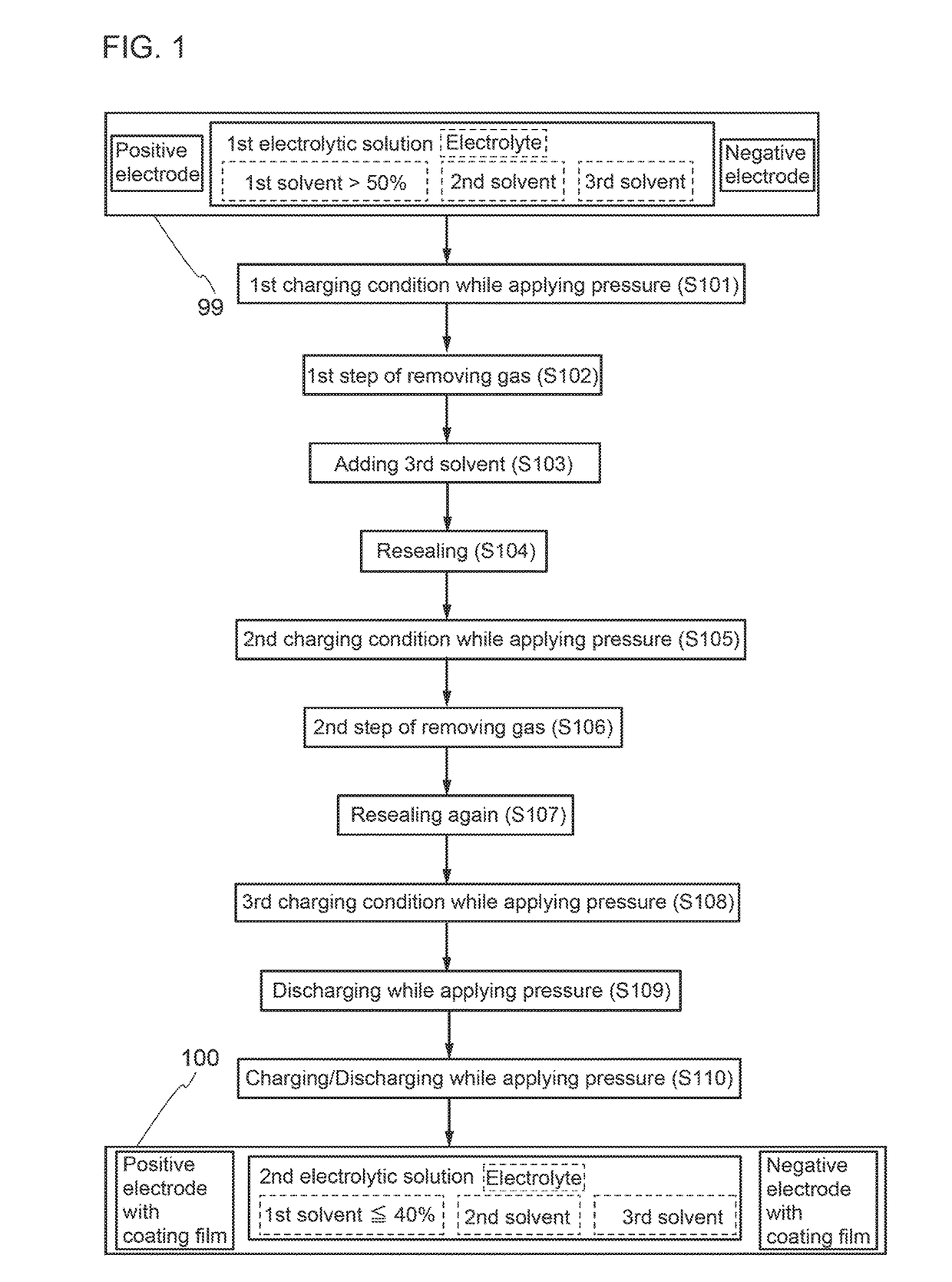
[0062]FIG. 1 is a flow chart showing an example of a fabrication process for a power storage device.

[0063]First, a first electrolytic solution is prepared. In this embodiment, an electrolyte (lithium salt) and three kinds of solvents are mixed to form the first electrolytic solution.

[0064]As the lithium salt, at least one of the following is used: LiPF6, LiN(FSO2)2 (abbreviation: LiFSA), LiClO4, LiAsF6, LiOH, LiCl, LiNO3, Li2SO4, LiBF4, LiCF3SO3, Li(CF3SO2)2N (abbreviation: LiTFSA), Li(C2F5SO2)2N (abbreviation: LiBETA), and the like.

[0065]As one of the three kinds of solvents (a first solvent), a cyclic carbonate, which is a high dielectric constant solvent, is used. Typically, ethylene carbonate is used. As the other two kinds of solvents (a second solvent and a third solvent), chain carbonates are used. Examples of a cyclic carbonate include ethylene carbonate and propylene carbonate. Examples of a chain carbonate include dimethyl carbonate, diethyl carbonate, and ethyl methyl car...

embodiment 2

[0108]FIG. 6 is a flow chart showing an example of a fabrication process for a power storage device that is different from the example in FIG. 1.

[0109]First, a first electrolytic solution is prepared. Although three kinds of solvents are mixed to form the first electrolytic solution in the fabrication procedure in Embodiment 1, two kinds of solvents are mixed to form the first electrolytic solution in this embodiment.

[0110]As a lithium salt, any of the lithium salts described in Embodiment 1 can be used.

[0111]As one of the two kinds of solvents (a first solvent), a cyclic carbonate, which is a high dielectric constant solvent, is used. Examples of a cyclic carbonate include ethylene carbonate (EC) and propylene carbonate. EC has a relative dielectric constant of 95.3 and a melting point of 36° C. and exhibits low viscosity at a temperature higher than the melting point. In this embodiment, EC is used as the first solvent.

[0112]As a second solvent, a chain carbonate is used. Examples...

embodiment 3

[0158]Described in this embodiment will be examples of electronic devices including the power storage devices described in Embodiment 1 and Embodiment 2.

[0159]FIGS. 10A to 10F illustrate other examples of electronic devices each including a power storage device. Examples of electronic devices each including a power storage device include television devices (also referred to as televisions or television receivers), monitors of computers or the like, cameras such as digital cameras and digital video cameras, digital photo frames, cellular phones (also referred to as mobile phones or mobile phone devices), portable game machines, portable information terminals, audio reproducing devices, and large game machines such as pachinko machines.

[0160]In addition, a power storage device can be incorporated along a curved inside / outside wall surface of a house or a building or a curved interior / exterior surface of a car.

[0161]FIG. 10A illustrates an example of a cellular phone. A cellular phone ...


PUM

PropertyMeasurementUnit
temperatureaaaaaaaaaa
relative dielectric constantaaaaaaaaaa

Abstract

In initial charge and discharge, decomposition products or a gas is generated, degrading a battery. At least one of solvents (e.g., ethylene carbonate) used for an electrolytic solution is brought into contact with a positive electrode and a negative electrode and then charge is performed to some degree, and after that, a different solvent or electrolytic solution (e.g., ethyl methyl carbonate or vinylene carbonate) was added to adjust the electrolytic solution and then charge is performed. Through this process, stable coating films are formed in initial charge and discharge, which stably inhibits a side reaction between the electrolytic solution and an active material.

Description

BACKGROUND OF THE INVENTION1. Field of the Invention[0001]One embodiment of the present invention relates to an object, a method, or a manufacturing method. The present invention relates to a process, a machine, manufacture, or a composition of matter. One embodiment of the present invention relates to a semiconductor device, a display device, a light-emitting device, a power storage device, a lighting device, an electronic device, or a manufacturing method thereof. In particular, one embodiment of the present invention relates to an electronic device and its operating system.[0002]Note that electronic devices in this specification generally mean devices including power storage devices, and electro-optical devices including power storage devices, information terminal devices including power storage devices, and the like are all electronic devices.2. Description of the Related Art[0003]Lithium-ion secondary battery as a type of power storage devices are used for a variety of applicat...

Claims


Application Information

Patent Timeline
Patent Type & Authority Applications(United States)
IPC IPC(8): H01M10/058H01M10/0567H01M10/0525H01M10/0568H01M10/0569H01M10/44
CPCH01M10/058H01M10/0525H01M10/0569H01M10/0568H01M10/446H01M10/0567H01M2300/004Y02E60/10Y02P70/50H01M10/049H01M10/44H01M2300/0028H01M2220/20H01M2220/30Y02T10/70
Inventor OGUNI, TEPPEIGOTO, JUNYANAKAGAWA, AI
Owner SEMICON ENERGY LAB CO LTD
Learn More