Electrical contact element

a contact element and electric technology, applied in the direction of connection contact member material, coupling contact member, electrical apparatus, etc., can solve the problems of increased vehicle weight, lowered electrical conductivity, aluminum is prone to oxidation, etc., and achieves good electrical conductivity, low density, and corrosion protection.

Active Publication Date: 2017-11-30
APTIV TECH LTD
View PDF1 Cites 5 Cited by
  • Summary
  • Abstract
  • Description
  • Claims
  • Application Information

AI Technical Summary

Benefits of technology

[0019]Punching or cutting to form the sheet metal may be performed at any step during deposition of the layers, although it is preferred to perform the punching or cutting of the sheet metal prior to the deposition of the layers so that the edges of the sheet metal are also coated with the coating, which leads to a better protection against corrosion.
[0020]The wire electrical cable preferably comprises aluminum or an alloy thereof, as aluminum has a low density and good electrical conductivity. Using aluminum lines leads to a lower vehicle weight and less emission of greenhouse gases. In order to ensure optimum conductivity between two or more mating electrical contact elements, the sheet metal may be made of copper or an alloy thereof. If the line comprises aluminum or an alloy thereof and the sheet metal is made of copper or an alloy thereof, tin may be a preferable material for the first layer, as its standard electrode potential is ranking between a standard electrode potential of the sheet metal material and a standard electrode potential of the wire electrical cable material. Preferably, the tin contained in the first layer is matte tin. In this context, the term “is made of a material” is to be understood as “consisting of this material and possibly some unavoidable impurities”.

Problems solved by technology

Yet, in vehicles, safety aspects and consumer demands require sophisticated electrical wiring leading to an increase in vehicle weight.
However, aluminum is prone to oxidation, when exposed to oxygen from ambient air, which will create a thin layer of electrically insulating aluminum oxide.
As a consequence electrical conductivity will be lowered, which, for example, may lead to malfunction of an electronic device fed via an aluminum line of the wiring.
When aluminum and copper are in contact in the presence of an electrolyte such as salt containing water, galvanic corrosion will occur due to the rather large difference in the standard electrode potentials of aluminum and copper.
This corrosion will lead to the consumption of the material having the lower standard electrode potential (here aluminum) and / or to the creation of a gap between the wire electrical cable and the electrical contact element, ultimately resulting in a poor quality of the contact between the wire electrical cable and the contact element.
However, as corrosion of the additional layer gradually proceeds, an electrically insulating layer is formed which in turn will increase the electrical resistance between the wire electrical cable and the electrical contact element and thereby deteriorate the quality of the contact between the contact element and the wire electrical cable.

Method used


Image

  • Electrical contact element
  • Electrical contact element
  • Electrical contact element

Examples


first embodiment

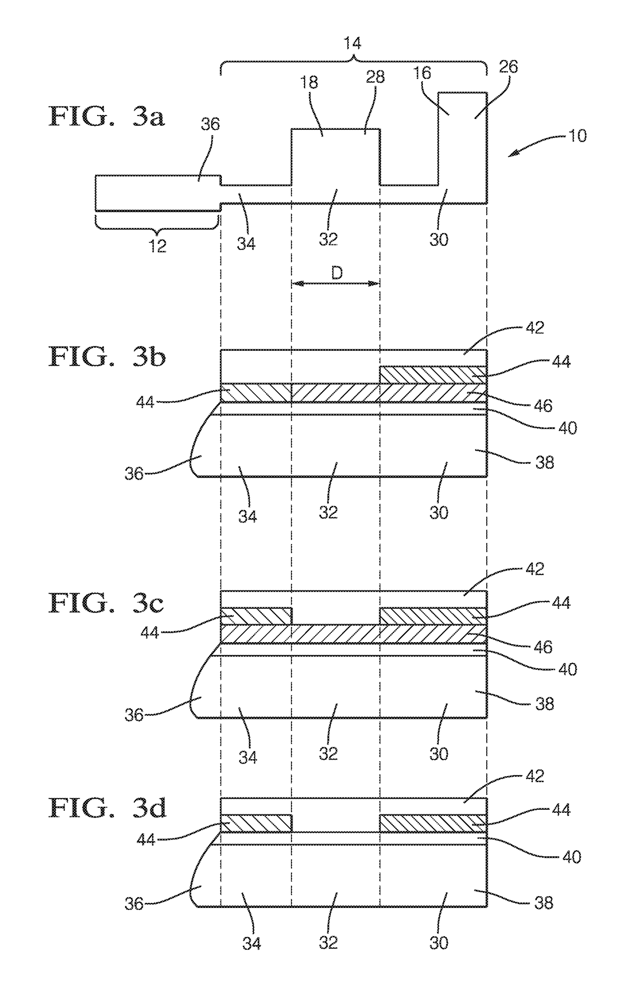
[0049] illustrated in FIG. 3b, the coating in the first region 30 contains a first layer 42, a second layer 44 and a third layer 46, wherein the first layer 42 forms an outer layer and the second layer 44 is arranged underneath the first layer 42. More specifically, the second layer 44 is provided between the first layer 42 and the third layer 46, wherein the third layer 46 is arranged on top of the layer 40 of hot dip tin.

[0050]In the second region 32, the coating contains the first layer 42 and the third layer 46. Again, the first layer 42 forms an outer layer and the third layer 46 is arranged on top of the layer 40 of hot dip tin. In contrast to the coating in the first region 30, the second layer 44 is absent in the coating in the second region 32.

[0051]In the third region 34, the coating contains the first layer 42 and the second layer 44, whereas the third layer 46 absent. In other words, the first layer 42 forms an outer layer and the second layer 44 is arranged between and ...

second embodiment

[0052]FIG. 3c shows a coating of the connection portion 14 according to a This coating differs from the coating shown in FIG. 3b in that a layer structure in the third region 34 corresponds to the layer structure in the first region 30, i.e. the third region 34 comprises not only the first and second layers 42, 44 but also the third layer 46 wherein the first layer 42 forms an outer layer and the second layer 44 is arranged between the first layer 42 and the third layer 46.

third embodiment

[0053]In FIG. 3d a coating of the connection portion 14 is depicted. This coating differs from the coating shown in FIG. 3c in that the third layer 46 is absent in the first, second and third regions 30, 32, 34.

[0054]In either case, the terminal portion 12 of the electrical contact element 10 does not comprise any coating of the sort described above, i.e. the layer 40 of hot dip tin forms an outer layer in the fourth region 36.

[0055]In all embodiments shown in FIGS. 3b to 3d, 4b and 5, the first layer 42 is made of matte tin. The second layer 44 is made of zinc. The third layer 46 is made of an alloy of copper and zinc, with the copper zinc alloy preferably containing zinc in an amount of 30% to 40% by weight.

[0056]As can be seen in FIGS. 3b to 3d, the first region 30 and the third region 34 comprise a coating containing the second layer 44, whereas the second layer 44 is absent in the second region 32. Compared to the standard electrode potentials of copper contained in the sheet ...


PUM

PropertyMeasurementUnit
distanceaaaaaaaaaa
distanceaaaaaaaaaa
distanceaaaaaaaaaa

Abstract

An electrical contact element formed of sheet metal having a first region and a second region. Each one of the first and second regions is coated with a coating including a first layer containing a first material having a lower standard electrode potential than the sheet metal material. The coating includes a second layer in the first region which is absent in the second region. The second layer is arranged underneath the first layer and contains a second material that has a lower standard electrode potential than the first material.

Description

CROSS-REFERENCE TO RELATED APPLICATION[0001]This application claims the benefit under 35 U.S.C. §119(a) of patent application Ser. No. 16 / 171,090.0 filed in the European Patent Office on May 24, 2016, the entire disclosure of which is hereby incorporated by reference.TECHNICAL FIELD OF THE INVENTION[0002]The present invention relates to an electrical contact element comprising a sheet metal made of a sheet metal material and having a first region and a second region, wherein each one of the first and second regions is coated with a coating including a first layer containing a first material having a lower standard electrode potential than the sheet metal material.BACKGROUND OF THE INVENTION[0003]More than ever, climate protection is a topic of great relevance. One effort in this field is directed to reduce fuel consumption of vehicles and to consequently lower emission of greenhouse gases such as carbon dioxide by decreasing the weight of a vehicle. Yet, in vehicles, safety aspects ...

Claims


Application Information

Patent Timeline
Patent Type & Authority Applications(United States)
IPC IPC(8): C23F13/00H01R13/03H01R4/64C23F13/16H01R4/26
CPCC23F13/005C23F13/16H01R4/26H01R4/64H01R13/03C23F2213/20C23F2213/30H01R4/62H01R4/185H01R43/16
Inventor GAERTNER, MARKUS
Owner APTIV TECH LTD
Why Eureka
Try Eureka